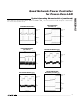
9-3428; Rev 1; 9/05 KIT ATION EVALU E L B A IL AVA Quad Network Power Controller for Power-Over-LAN Features The MAX5945 quad network power controller is designed for use in IEEE 802.3af-compliant power-sourcing equipment (PSE). The device provides power devices (PD) discovery, classification, current-limit, and both DC and AC load disconnect detections. The MAX5945 can be used in either endpoint PSE (LAN switches/routers) or midspan PSE (power injector) applications.
MAX5945 Quad Network Power Controller for Power-Over-LAN ABSOLUTE MAXIMUM RATINGS (Voltages referenced to VEE, unless otherwise noted.) AGND, DGND, DET_, VDD, RESET, A3, A2, A1, A0, SHD_, OSC_IN, SCL, SDAIN, OUT_ and AUTO............-0.3V to +80V GATE_ (internally clamped, Note 1)....................-0.3V to +11.4V SENSE_ ..................................................................-0.3V to +24V VDD, RESET, A3, A2, A1, A0, SHD_, OSC_IN, SCL, SDAIN and AUTO to DGND .....................................
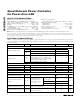
Quad Network Power Controller for Power-Over-LAN (AGND = +32V to +60V, VEE = 0V, VDD to DGND = +3.3V, all voltages are referenced to VEE, unless otherwise noted. Typical values are at AGND = +48V, DGND = +48V, VDD = (DGND + 3.3V), TA = +25°C. Currents are positive when entering the pin and negative otherwise.
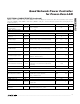
MAX5945 Quad Network Power Controller for Power-Over-LAN ELECTRICAL CHARACTERISTICS (continued) (AGND = +32V to +60V, VEE = 0V, VDD to DGND = +3.3V, all voltages are referenced to VEE, unless otherwise noted. Typical values are at AGND = +48V, DGND = +48V, VDD = (DGND + 3.3V), TA = +25°C. Currents are positive when entering the pin and negative otherwise.) PARAMETER SYMBOL CONDITIONS MIN TYP MAX UNITS AC Load Disconnect Threshold (Note 4) IACTH Current into DET_, ACD_EN_ bit = high, OSC_IN = 2.
Quad Network Power Controller for Power-Over-LAN (AGND = +32V to +60V, VEE = 0V, VDD to DGND = +3.3V, all voltages are referenced to VEE, unless otherwise noted. Typical values are at AGND = +48V, DGND = +48V, VDD = (DGND + 3.3V), TA = +25°C. Currents are positive when entering the pin and negative otherwise.
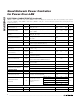
ELECTRICAL CHARACTERISTICS (continued) (AGND = +32V to +60V, VEE = 0V, VDD to DGND = +3.3V, all voltages are referenced to VEE, unless otherwise noted. Typical values are at AGND = +48V, DGND = +48V, VDD = (DGND + 3.3V), TA = +25°C. Currents are positive when entering the pin and negative otherwise.) PARAMETER SYMBOL CONDITIONS MIN TYP MAX Setup Time for a Repeated START Condition (Sr) tSU, STA (Note 9) 0.
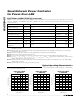
Quad Network Power Controller for Power-Over-LAN DIGITAL SUPPLY CURRENT vs. INPUT VOLTAGE VEE UNDERVOLTAGE LOCKOUT vs. TEMPERATURE 3 2 9.96 9.94 29.0 28.5 28.0 1 27.5 0 27.0 MAX5945 toc06 29.5 GATE OVERDRIVE (V) 4 9.98 MAX5945 toc05 5 UNDERVOLTAGE LOCKOUT (V) MEASURED AT VDD SUPPLY CURRENT (mA) 30.0 MAX5945 toc04 6 GATE OVERDRIVE vs. INPUT VOLTAGE 9.92 9.90 9.88 9.86 9.84 9.82 9.80 2.6 3.0 3.4 3.8 4.2 4.6 9.
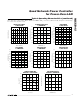
MAX5945 Quad Network Power Controller for Power-Over-LAN Typical Operating Characteristics (continued) (VEE = -48V, VDD = +3.3V, AUTO = AGND = DGND = 0V, RESET = SHD_ = unconnected, RSENSE = 0.5Ω, all registers = default setting, TA = +25°C, unless otherwise noted.
Quad Network Power Controller for Power-Over-LAN STARTUP WITH VALID PD (25kΩ AND 0.
MAX5945 Quad Network Power Controller for Power-Over-LAN Typical Operating Characteristics (continued) (VEE = -48V, VDD = +3.3V, AUTO = AGND = DGND = 0V, RESET = SHD_ = unconnected, RSENSE = 0.5Ω, all registers = default setting, TA = +25°C, unless otherwise noted.
Quad Network Power Controller for Power-Over-LAN PIN NAME FUNCTION 1 RESET Hardware Reset. Pull RESET low for at least 300µs to reset the device. All internal registers reset to their default value. The address (A0–A3), and AUTO and MIDSPAN input logic levels latch on during low-to-high transition of RESET. Internally pulled up to VDD with 50kΩ resistor. 2 MIDSPAN MIDSPAN Mode Input. An internal 50kΩ pulldown resistor to DGND sets the default mode to endpoint PSE operation (power-over-signal pairs).
MAX5945 Quad Network Power Controller for Power-Over-LAN VDD SCL SDAIN SDAOUT OSC_IN DGND SHD_ CURRENT SENSING VOLTAGE PROBING AND CURRENT-LIMIT CONTROL OSCILLATOR MONITOR SERIAL PORT INTERFACE (SPI) DET_ A0 DETECTION/ CLASSIFICATION SM A1 9-BIT ADC CONVERTER VOLTAGE SENSING OUT_ 10V ACD_ENABLE PORT STATE MACHINE (SM) A2 REGISTER FILE A3 50µA A=3 GATE_ AUTO PWR_EN MIDSPAN CENTRAL LOGIC UNIT (CLU) AC DISCONNECT SIGNAL (ACD) RESET 13V CLAMP AC DETECTION FAST DISCHARGE CONTROL 100mA 90µ
Quad Network Power Controller for Power-Over-LAN Reset Reset is a condition the MAX5945 enters after any of the following conditions: • After power-up (VEE and VDD rise above their UVLO thresholds). • Hardware reset. The RESET input is driven low and up high again any time after power-up. • Software reset. Writing a 1 into R1Ah[4] any time after power-up. • Thermal shutdown.
MAX5945 Quad Network Power Controller for Power-Over-LAN Setting R19h[PWR_ON_] (Table 21) high immediately terminates detection/classification routines and turns on power to the port(s). R14h[DET_EN_, CLASS_EN_] default to low in SEMI mode. Use software to set R14h[DET_EN_, CLASS_EN_] to high to start the detection and/or classification routines. R14h[DET_EN_, CLASS_EN_] are reset every time the software commands a power-off of the port (either through reset or PWR_OFF).
Quad Network Power Controller for Power-Over-LAN MAX5945 Table 1. PSE PI Detection Modes Electrical Requirement (Table 33-2 of the IEEE 802.3af Standard) PARAMETER SYMBOL MIN MAX Open-Circuit Voltage VOC — 30 V In detection mode only Short-Circuit Current ISC — 5 mA In detection mode only Valid Test Voltage VVALID 2.8 10 V Voltage Difference Between Test Points ∆VTEST 1 — V Time Between Any Two Test Points tBP 2 — ms Slew Rate VSLEW — 0.
Quad Network Power Controller for Power-Over-LAN MAX5945 Overcurrent Protection 80ms 0V 150ms 150ms tDETI tDETII 21.3ms tCLASS 0V -4V -9V OUT_ -18V -48V Figure 2. Detection, Classification, and Power-Up Port Sequence POK tPGOOD t A sense resistor (RS), connected between SENSE_ and V EE , monitors the load current. Under all circumstances, the voltage across R S never exceeds the threshold V SU_LIM.
Quad Network Power Controller for Power-Over-LAN VSU_LIM VSU_LIM / 3 30V 50V (VOUT_ - VEE) Figure 4. Foldback Current Characteristics digital supply for compatibility with the internal logic. The MAX5945 also features a VDD undervoltage lockout (VDDUVLO) of +1.35V. A VDDUVLO condition keeps the MAX5945 in reset and the ports shut off. Bit 0 in the supply event register shows the status of V DDUVLO (Table 11) after VDD has recovered. All logic inputs and outputs reference to DGND.
MAX5945 Quad Network Power Controller for Power-Over-LAN The MAX5945 also features three other undervoltage and overvoltage interrupts: VEE undervoltage interrupt (VEEUV), VDD undervoltage interrupt (VDDUV), and VDD overvoltage interrupt (VDDOV). A fault latches into the supply events register (Table 11) but the MAX5945 does not shut down the ports with a VEEUV, VDDUV, or VDDOV. DC Disconnect Monitoring Setting R13h[DCD_EN_] bits high enable DC load monitoring during a normal powered state.
Quad Network Power Controller for Power-Over-LAN MAX5945 SDAIN tBUF tSU, DAT tLOW tSU, STA tHD, STA tSU, STO tHD, DAT SCL tHIGH tHD, STA tR tF START CONDITION REPEATED START CONDITION STOP CONDITION START CONDITION Figure 5. 2-Wire Serial Interface Timing Details SDAIN/SDA tBUF tSU, DAT tLOW tSU, STA tHD, STA tSU, STO tHD, DAT SCL tHIGH tHD, STA tR tF START CONDITION REPEATED START CONDITION STOP CONDITION START CONDITION Figure 6.
MAX5945 Quad Network Power Controller for Power-Over-LAN CLOCK PULSE FOR ACKNOWLEDGEMENT START CONDITION 1 SCL 2 8 9 SDA BY TRANSMITTER S SDA BY RECEIVER Figure 9. Acknowledge MSB SDA 0 LSB 1 0 A3 A2 A1 A0 R/W ACK SCL Figure 10. Slave Address Bit Transfer Each clock pulse transfers one data bit (Figure 8). The data on SDA must remain stable while SCL is high.
Quad Network Power Controller for Power-Over-LAN S SLAVE ADDRESS 0 D15 D14 D13 A D12 D11 D10 D9 MAX5945 CONTROL BYTE IS STORED ON RECEIPT OF STOP CONDITION ACKNOWLEDGE FROM MAX5945 D8 CONTROL BYTE A P ACKNOWLEDGE FROM MAX5945 R/W Figure 11.
MAX5945 Quad Network Power Controller for Power-Over-LAN Table 4. Auto-Increment Rules COMMAND BYTE ADDRESS RANGE AUTO-INCREMENT BEHAVIOR 0x00 to 0x26 Command address will autoincrement after byte read or written 0x26 Command address remains at 0x26 after byte written or read Message Format for Reading The MAX5945 reads using the MAX5945’s internally stored command byte as an address pointer, the same way the stored command byte is used as an address pointer for a write.
Quad Network Power Controller for Power-Over-LAN MAX5945 Table 5. Interrupt Register ADDRESS = 00h DESCRIPTION SYMBOL BIT R/W SUP_FLT 7 R Interrupt signal for supply faults. SUP_FLT is the logic OR of all the bits [7:0] in register R0Ah/R0Bh (Table 8). TSTR_FLT 6 R Interrupt signal for startup failures. TSRT_FLT is the logic OR of bits [7:0] in register R08h/R09h (Table 7). IMAX_FLT 5 R Interrupt signal for current-limit violations.
MAX5945 Quad Network Power Controller for Power-Over-LAN Table 7.
Quad Network Power Controller for Power-Over-LAN MAX5945 Table 10.
MAX5945 Quad Network Power Controller for Power-Over-LAN Table 12a. Detection Result Decoding Chart DET_ST_[2:0] DETECTED 000 None Detection status unknown DESCRIPTION 001 DCP Positive DC supply connected at the port (AGND - VOUT_ < 1.65V) 010 HIGH CAP 011 RLOW 100 DET_OK 101 RHIGH High resistance at the port. RPD > 28kΩ. 110 OPEN0 Open port (I < 12.5µA) 111 DCN High capacitance at the port (>5µF) Low resistance at the port. RPD < 17kΩ. Detection pass. 17kΩ > RPD > 28kΩ.
Quad Network Power Controller for Power-Over-LAN MAX5945 Table 13. Power Status Register ADDRESS = 10h DESCRIPTION SYMBOL BIT R/W PGOOD4 7 R Power-good condition on port 4 PGOOD3 6 R Power-good condition on port 3 PGOOD2 5 R Power-good condition on port 2 PGOOD1 4 R Power-good condition on port 1 PWR_EN4 3 R Power is enabled on port 4 PWR_EN3 2 R Power is enabled on port 3 PWR_EN2 1 R Power is enabled on port 2 PWR_EN1 0 R Power is enabled on port 1 Table 14.
MAX5945 Quad Network Power Controller for Power-Over-LAN In MANUAL mode, R14h works like a pushbutton. Set the bits high to begin the corresponding routine. The bit clears after the routine finishes. When entering AUTO mode, R14h defaults to FFh. When entering MANUAL mode, R14h defaults to 00h. When entering SEMI mode, R1h is left unchanged but it is reset every time the software commands power off the port.
Quad Network Power Controller for Power-Over-LAN MAX5945 Table 18. Backoff Enable Register ADDRESS = 15h DESCRIPTION SYMBOL BIT R/W Reserved 7 R Reserved Reserved 6 R Reserved Reserved 5 R Reserved Reserved 4 R Reserved BCKOFF4 3 R/W Enable Cadence timing on port 4 BCKOFF3 2 R/W Enable Cadence timing on port 3 BCKOFF2 1 R/W Enable Cadence timing on port 2 BCKOFF1 0 R/W Enable Cadence timing on port 1 Table 19.
MAX5945 Quad Network Power Controller for Power-Over-LAN Table 20.
Quad Network Power Controller for Power-Over-LAN MAX5945 Table 23. ID Register ADDRESS = 1Bh SYMBOL ID_CODE REV DESCRIPTION BIT R/W 7 R ID_CODE[4] 6 R ID_CODE[3] 5 R ID_CODE[2] 4 R ID_CODE[1] 3 R ID_CODE[0] 2 R REV [2] 1 R REV [1] 0 R REV [0] ID register keeps track of the device ID number and revision. The MAX5945’s ID_CODE[4:0] = 11000b. Contact the factory for REV[2:0] value. Table 24.
MAX5945 Quad Network Power Controller for Power-Over-LAN Table 25. Watchdog Timer Register ADDRESS = 1Eh SYMBOL WDTIME DESCRIPTION BIT R/W 7 R/W WDTIME[7] 6 R/W WDTIME[6] 5 R/W WDTIME[5] 4 R/W WDTIME[4] 3 R/W WDTIME[3] 2 R/W WDTIME[2] 1 R/W WDTIME[1] 0 R/W WDTIME[0] Table 26.
Quad Network Power Controller for Power-Over-LAN MAX5945 Table 27. Program Register 1 ADDRESS = 23h SYMBOL IGATE DESCRIPTION BIT R/W 7 R/W IGATE[2] 6 R/W IGATE[1] 5 R/W IGATE[0] DET_BYP 4 R/W Detect bypass protection in AUTO mode OSCF_RS 3 R/W OSC_FAIL Reset Bit 2 R/W AC_TH[2] 1 R/W AC_TH[1] 0 R/W AC_TH[0] AC_TH Table 28. Program Register 2 ADDRESS = 27h SYMBOL IMAX TD_PR DESCRIPTION BIT R/W 7 R IMAX[3]. VSU_LIM programming bit 3. 6 R IMAX[2].
MAX5945 Quad Network Power Controller for Power-Over-LAN Table 29. Program Register 3 ADDRESS = 28h SYMBOL TF_PR TS_PR DESCRIPTION BIT R/W 7 R TF_PR[3]. tFAULT nominal programming bit 3. 6 R TF_PR[2]. tFAULT nominal programming bit 2. 5 R TF_PR[1]. tFAULT nominal programming bit 1. 4 R TF_PR[0]. tFAULT nominal programming bit 0. 3 R TS_PR[3]. tSTART nominal programming bit 3. 2 R TS_PR[2]. tSTART nominal programming bit 2. 1 R TS_PR[1]. tSTART nominal programming bit 1.
REGISTER NAME Int Mask 01h RO CoR RO CoR RO CoR RO CoR Detect Event Detect Event CoR Fault Event Fault Event CoR Tstart Event Tstart Event CoR Supply Event Supply Event CoR 03h 04h 05h 06h 07h 08h 09h 0Ah 0Bh ______________________________________________________________________________________ Port 2 Status Port 3 Status Port 4 Status Power Status Pin Status 0Dh 0Eh 0Fh 10h 11h RO RO RO RO RO G 4321 4 3 2 1 4321 4321 4321 4321 4321 G G PORT reserved
REGISTER NAME R/W R/W Det/Class Enable Backoff Enable Timing Config Misc Config 14h 15h 16h 17h Global 19h 1Ah Switch Mode 1FH ______________________________________________________________________________________ Reserved Reserved Program1 Reserved Reserved Reserved Program2 Program3 21H 22H 23H 24h 25h 26h 27H 28H R/W R/W R/W R/W R/W CoR RO WO WO R/W R/W G G G G G 4321 G G G 4321 G G 4321 G G 4321 G G G 4321 4321 4321 4321 PORT TF_PR[
Quad Network Power Controller for Power-Over-LAN PSE (SWITCHES/ROUTERS, ETC) DATA RJ–45 PHY POWER MAX5020 GND PD (IP PHONE, WIRELESS ACCESS POINT, SECURITY CAMERAS, ETC.) 3.3V -48V TO +3.3V DC-DC DATA RJ–45 POWER AND DATA OVER TWISTED-PAIR ETHERNET CABLE PHY LOAD POWER MAX5945 MAX5940B QUAD PoE CONTROLLER PD INTERFACE CONTROLLER -48V MAX5014 DC-DC CONVERTER VOUT OR -48V MAX5941/MAX5942 PD INTERFACE AND DC-DC CONVERTER Figure 14.
MAX5945 Quad Network Power Controller for Power-Over-LAN RJ–45 CONNECTOR 1 3 RX1+ RD1+ RX1- RD1- 24 1 22 2 1/2 OF 21 H2005A TX1+ 4 TD1+ 19 TX1- PHY 5 3 6 TD1- -48VOUT 0.1µF RXT1 75Ω 23 4 0.1µF 5 1000pF 250VAC 0.1µF TXCT1 75Ω 75Ω 20 75Ω 7 0.1µF 8 -48VRTN VCC (3.3V) VDD ISOLATION 1.8V TO 5V, (REF TO DGND) 3kΩ AGND VDD 180Ω A0 A1 A2 A3 1kΩ RESET INTERNAL 50kΩ PULLUP 3kΩ HPCL063L SERIAL INTERFACE VCCRTN 4.
Quad Network Power Controller for Power-Over-LAN MAX5945 RJ–45 CONNECTOR 1 2 DATA 3 6 4 5 7 8 -48VOUT -48VRTN VCC (3.3V) VDD ISOLATION 1.8V TO 5V (REF TO DGND) 3kΩ AGND VDD 180Ω A0 A1 A2 A3 1kΩ RESET INTERNAL 50kΩ PULLUP 3kΩ HPCL063L SERIAL INTERFACE VCCRTN 4.7kΩ INT SDAOUT OPTIONAL BUFFER 180Ω SDAIN OPTIONAL BUFFER 180Ω INTERNAL PULLDOWN (MANUAL MODE) MIDSPAN INTERNAL PULLDOWN (SIGNAL MODE) MAX5945 HPCL063L SDA AUTO 3kΩ OSC_IN SINE WAVE 100Hz ±10% PEAK AMPLITUDE 2.2V ±0.
MAX5945 Quad Network Power Controller for Power-Over-LAN R10 2Ω L1 68µH, DO3308P-683 R6 1Ω D1 DIODES INC.: B1100 C3 15nF C4 220µF Sanyo 6SPS220M R5 1kΩ R1 2.6kΩ +3.3V 300mA C5 4.7µF Q2 MMBTA56 Q4 MMBTA56 GND +3.3V GND GND DRAIN 1 2 3 C6 0.47µF 100V 4 V+ MAX5020 VCC VDD NDRV FB GND CS SS_SHDN 8 R8 30Ω 7 6 Q3 MMBTA56 Q1 Si2328 DS C9 4.7µH SOURCE 5 C7 0.22µF C1 0.1µF C2 0.022µF GATE C8 2.2µF R4 1Ω -48V R9 1Ω R2 6.81kΩ R7 1.02kΩ R3 2.61kΩ -48V Figure 17. -48V to +3.
Quad Network Power Controller for Power-Over-LAN DESIGNATION C1 DESCRIPTION 0.1µF, 25V ceramic capacitor C2 0.022µF, 25V ceramic capacitor C3 15nF, 25V ceramic capacitor C4 220µF capacitor Sanyo 6SVPA220MAA C5 4.7µF, 16V ceramic capacitor C6 0.1µF, 100V ceramic capacitor C7 0.22µF, 16V ceramic capacitor C8 0.22µF, 16V ceramic capacitor C9 4.
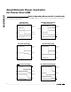
Quad Network Power Controller for Power-Over-LAN MAX5945 Typical Operating Circuits -48V RTN OUTPUT TO PORT -48VRTN VCC (3.3V) ISOLATION VDD 1.8V TO 3.7V, (REF TO DGND) 3kΩ AGND VDD 180Ω A0 A1 A2 A3 1kΩ RESET 3kΩ INTERNAL 50kΩ PULLUP SERIAL INTERFACE VCCRTN HPCL063L 180Ω SDAOUT OPTIONAL BUFFER INT 3kΩ AUTO INTERNAL PULLDOWN (MANUAL MODE) MIDSPAN INTERNAL PULLDOWN (SIGNAL MODE) SDAIN MAX5945 HPCL063L SDA OPTIONAL BUFFER 180Ω 4.7kΩ OSC_IN 3kΩ N.C.
Quad Network Power Controller for Power-Over-LAN -48V RTN OUTPUT TO PORT -48VRTN VCC (3.3V) VDD ISOLATION 1.8V TO 3.7V, (REF TO DGND) 3kΩ AGND VDD 180Ω A0 A1 A2 A3 1kΩ RESET INTERNAL 50kΩ PULLUP 3kΩ HPCL063L SERIAL INTERFACE VCCRTN 4.7kΩ INT SDAOUT OPTIONAL BUFFER 180Ω 3kΩ SDAIN MAX5945 HPCL063L SDA OPTIONAL BUFFER 180Ω AUTO INTERNAL PULLDOWN (MANUAL MODE) MIDSPAN INTERNAL PULLDOWN (SIGNAL MODE) OSC_IN SINE WAVE 100Hz ±10% PEAK AMPLITUDE 2.2V ±0.1V VALLEY AMPLITUDE 0.2V ±0.
Package Information (The package drawing(s) in this data sheet may not reflect the most current specifications. For the latest package outline information, go to www.maxim-ic.com/packages.) SSOP.EPS MAX5945 Quad Network Power Controller for Power-Over-LAN 36 E DIM A A1 B C e E H L D H INCHES MILLIMETERS MAX MIN 0.096 0.104 0.004 0.011 0.012 0.017 0.013 0.009 0.0315 BSC 0.299 0.291 0.398 0.414 0.040 0.020 0.598 0.612 MAX MIN 2.65 2.44 0.29 0.10 0.44 0.30 0.23 0.32 0.80 BSC 7.40 7.60 10.11 10.51 0.