
Instruction Manual

0V to 16V, Dual Hot-Swap Controller with 10-Bit
Current and Voltage Monitor and 4 LED Drivers
MAX5970
_______________________________________________________________________________________ 9
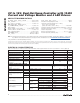
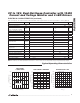
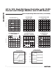
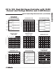
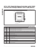
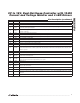
Pin Description (continued)
PIN NAME FUNCTION
14 LED1 LED Driver 1
15 LED2 LED Driver 2
16 POL
Polarity Select Input. Connect to DREG for active-high power-good outputs (PG_). Connect to GND for
active-low power-good outputs.
17 DREG
Logic Power-Supply Input. Connect to REG externally through a 10I resistor and to DGND with a 1FF
ceramic capacitor.
18 ON1 Channel 1 Precision Turn-On Input
19
FAULT1 Channel 1 Active-Low Open-Drain Fault Output. FAULT1 goes low if an overcurrent occurs on channel 1.
20
FAULT2 Channel 2 Active-Low Open-Drain Fault Output. FAULT2 goes low if an overcurrent occurs on channel 2.
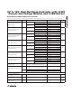
21 SDA I
2
C Serial-Data Input/Output
22 SCL I
2
C Serial-Clock Input
23
ALERT Open-Drain Alert Output. ALERT goes low during a fault to notify the system of an impending failure.
24 PG1 Channel 1 Open-Drain Power-Good Output
25 PG2 Channel 2 Open-Drain Power-Good Output
26 HWEN
Hardware Enable Input. Connect to DREG or DGND. State is read upon power-up as V
IN
crosses the
UVLO threshold and sets enable register bits with this value. After UVLO, this input becomes inactive until
power is cycled.
27 DGND Digital Ground. Connect all GND_ and DGND to AGND externally using a star connection.
28 ON2 Channel 2 Precision Turn-On Input
29 RETRY
Autoretry Fault Management Input. Connect to DREG to enable autoretry operation. Connect to DGND to
enable latched-off operation.
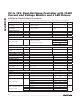
30 MODE
Hot-Swap Two-State Mode Select Input. Connect MODE to DGND, DREG or leave it unconnected to oper-
ate the hot-swap channels independently or as a pair.
31 LED4 LED Driver 4
32 LED3 LED Driver 3
33 GND2
Channel 2 Gate Discharge Current Ground Return. Connect all GND_ and DGND to AGND externally
using a star connection.
34 GATE2 Channel 2 Gate-Drive Output. Connect to gate of an external n-channel MOSFET.
35 MON2 Channel 2 Voltage Monitoring Input
36 SENSE2
Channel 2 Current-Sense Input. Connect SENSE2 to the source of an external MOSFET and to one end of
R
SENSE2
.
— EP Exposed Pad. EP is internally grounded. Connect externally to ground plane using a star connection.