
Owner manual
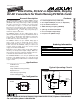

MAX606/MAX607
Low-Profile, 5V/12V or Adjustable, Step-Up
DC-DC Converters for Flash Memory/PCMCIA Cards
8 _______________________________________________________________________________________
Detailed Description
The remainder of this document contains the detailed
information you’ll need to design a circuit that differs
from the two Standard Application Circuits. If you are
using one of the predesigned circuits, the following
sections are purely informational.
The MAX606/MAX607 CMOS, step-up DC-DC convert-
ers employ a current-limited pulse-frequency control
scheme. This control scheme regulates a boost topolo-
gy to convert input voltages between 3V and 5.5V into
either a pin-programmable 5V/12V output, or an
adjustable output between V
IN
and 12.5V. It optimizes
performance over all input and output voltages, and
guarantees output accuracy to ±4%.
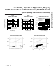
The ultra-high switching frequency (typically 1MHz for
the MAX606 and 0.5MHz for the MAX607) permits the
use of extremely small external components, making
these converters ideal for use in Types 1, 2, and 3 flash
memory and PCMCIA applications.
Pulse-Frequency-Modulation
Control Scheme
The MAX606/MAX607 employ a proprietary, current-
limited control scheme that combines the ultra-low sup-
ply current of traditional pulse-skipping converters with
the high full-load efficiency of current-mode pulse-
width-modulation converters. This particular control
scheme is similar to the one used in previous current-
limited devices (which governed the switching current
via maximum on-time, minimum off-time, and current
limit), except it varies the on and off times according to
the input and output voltages. This important feature
enables the MAX606/MAX607 to achieve ultra-high
switching frequencies while maintaining high output
accuracy, low output ripple, and high efficiency over a
wide range of loads and input/output voltages.
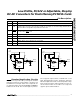
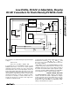
Figure 3 shows the functional diagram of the MAX606/
MAX607. The internal power MOSFET is turned on when
the error comparator senses that the output is out of reg-
ulation. The power switch stays on until either the timing
circuit turns it off at the end of the on-time, or the switch
current reaches the current limit. Once off, the switch
remains off during the off-time. Subsequently, if the out-
put is still out of regulation, another switching cycle is ini-
tiated. Otherwise, the switch remains turned off as long
as the output is in regulation.
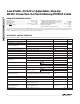
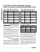
Table 1. Suggested Components for 12V
Standard Application Circuit of Figure 2
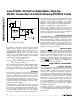
Table 2. Suggested Components for 5V
Standard Application Circuit of Figure 1
DESIGNATION MAX606 MAX607
L1
5µH inductor
Dale ILS-3825-XX
10µH inductor
Sumida CLS62-100
D1
0.5A, 20V diode
Motorola MBR0520L
0.5A, 20V diode
Motorola MBR0520L
C1 0.1µF ceramic cap. 0.1µF ceramic cap.
C2
2 x 0.68µF ceramic cap.
Marcon
THCR20E1E684Z
2.2µF ceramic cap.
Marcon
THCR30E1E225M
C3
2 x 0.68µF ceramic cap.
Marcon
THCR20E1E684Z
2 x 1µF ceramic cap.
Marcon
THCR30E1E105M
C4 10nF ceramic cap. 10nF ceramic cap.
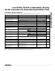
SUPPLIER PHONE FAX
Dale Inductors 605-668-4131 605-665-1627
Marcon/United
Chemi-Con
708-696-2000 708-518-9985
Sumida USA 708-956-0666 708-956-0702
Sumida Japan 03-607-5111 03-607-5144
Table 3. Component Suppliers
DESIGNATION MAX606 MAX607
L1
5µH, 1A inductor
Dale ILS-3825-XX
10µH, 0.7A inductor
Sumida CLS62B-100
D1
0.5A, 20V diode
Motorola MBR0520L
0.5A, 20V diode
Motorola MBR0520L
C1 0.1µF ceramic cap. 0.1µF ceramic cap.
C2
2 x 0.68µF ceramic cap.
Marcon
THCR20E1E684Z
2.2µF ceramic cap.
Marcon
THCR30E1E225M
C3
4.7µF ceramic cap.
Marcon
THCR30E1E475M
4.7µF ceramic cap.
Marcon
THCR30E1E475M
C4 10nF ceramic cap. 10nF ceramic cap.
Motorola 602-244-3576 602-244-4015