
User guide


+127°C, for T
LOW
is -55°C, for T
MAX
is +100°C, and for
T
HYST
is +95°C.
Overtemperature Output (
OVERT
)
The MAX6661 has an overtemperature output (OVERT)
that is set when the remote-diode temperature crosses
the limits set in the T
MAX
register. It is always active if
the remote-diode temperature exceeds T
MAX
. The
OVERT line clears when the temperature drops below
T
HYST
. Bit 1 of the configuration register can be used to
mask the OVERT output. Typically, the OVERT output is
connected to a power-supply shutdown line to turn sys-
tem power off. At power-up, OVERT defaults to low
when activated but the logic can be reversed by setting
bit 5 of the configuration register. If reversed, OVERT is
a logic one when the t
MAX
register temperature value is
exceeded. The OVERT line can be taken active, either
by the MAX6661 or driven by an external source.
OVERT also acts as an input when set to go low when
activated (default). If OVERT is driven or forced low
externally, the fan loop forces the fan to full speed and
bit 1 of the status register is set. The OVERT input can
be masked out by bit 2 of the configuration register.
Diode Fault Alarm
A continuity fault detector at DXP detects an open cir-
cuit between DXP and DXN. If an open or short circuit
exists, register 83h is loaded with 1000 0000.
Additionally, if the fault is an open circuit, bit 2 of the
status byte is set to 1 and the ALERT condition is acti-
vated at the end of the conversion. Immediately after
POR, the status register indicates that no fault is pre-
sent until the end of the first conversion.
ALERT
Interrupts
The ALERT interrupt output signal is activated (unless it
is masked by bit 7 in the configuration register) when-
ever the remote-diode’s temperature is below T
LOW
or
exceeds T
HIGH
. A disconnected remote diode (for con-
tinuity detection), a shorted diode, or an active OVERT
also activates the ALERT signal. The activation of the
ALERT signal sets the corresponding bits in the status
register. Once activated, ALERT is latched until
cleared. To clear the ALERT, read the status register.
The interrupt does not halt automatic conversions. New
temperature data continues to be available over the SPI
interface after ALERT is asserted. ALERT is an active-
low open-drain output so that devices can share a
common interrupt line. The interrupt is updated at the
end of each temperature conversion so, after being
cleared, it reappears after the next temperature conver-
sion if the cause of the fault has not been removed.
By setting bit 0 in the configuration register to 1, the
ALERT line always remains high. Prior to taking correc-
tive action, always check to ensure that an interrupt is
valid by reading the current temperature and the status
register.
Example: The remote temperature reading crosses
T
HIGH
, activating ALERT. The host responds to the
interrupt by reading the status register, clearing the
interrupt. If the condition persists, the interrupt reap-
pears.
One Shot
The one-shot command immediately forces a new con-
version cycle to begin. In software standby mode
(RUN/STOP bit = high), a new conversion is begun by
writing an OSHT (9Eh) command. After the conversion,
the device returns to standby mode. If a conversion is
in progress when a one-shot command is received, the
command is ignored. If a one-shot command is
between conversions in autoconvert mode (RUN/STOP
bit = low), a new conversion begins immediately.
Configuration Register Functions
The configuration register table (Table 4) describes this
register’s bit assignments.
Status Register Functions
The status byte (Table 5) reports several fault condi-
tions. It indicates when the fan driver transistor of the
MAX6661 has overheated and/or in thermal shutdown,
when the temperature thresholds, T
LOW
and T
HIGH
,
have been exceeded, and whether there is an open cir-
cuit in the DXP-DXN path. The register also reports the
state of the ALERT and OVERT lines and indicates
when the fan driver is fully on. The final bit in the status
register indicates when a fan failure has occurred.
After POR, the normal state of the flag bits is zero,
assuming no alert or overtemperature conditions are
MAX6661
Remote Temperature-Controlled Fan-Speed
Regulator with SPI-Compatible Interface
______________________________________________________________________________________ 11
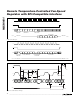
TEMP (°C) DIGITAL OUTPUT
+127 0111 1111 111
+125.00 0111 1101 000
+25 0001 1001 000
+0.125 0000 0000 001
0 0000 0000 000
-0.125 1111 1111 111
-25 1110 0111 111
-40 1101 1000111
Table 3. Temperature Data Format
(Two’s Complement)