
User guide


MAX6661
In thermal open-loop mode, the fan loop can operate in
open or closed mode. In fan open loop, the FSC regis-
ter programs fan voltage directly, accepting values
from 0 to 64 (40h). For example, in fan open-loop
mode, zero corresponds to no voltage across the fan
and 40h corresponds to full fan voltage. Proportional
control is available over the 0 to 63 (3Fh) range with 64
(40h) forcing unconditional full speed.
In fan closed-loop mode, zero corresponds to zero fan
speed. When the FG register is set to 4 bits, 10h corre-
sponds to 100% fan speed; 100% fan speed is 20h at 5
bits, and 3Fh at 6 bits.
Fan Loop
The fan loop (Figure 7) is based on an up/down counter
where a reference clock representing the desired fan
speed drives the count up, while tachometer pulses
drive it down. The reference clock frequency is divided
down from the MAX6661 internal clock to a frequency
of 8415Hz. This clock frequency is further divided by
the fan full-scale (FS) register (Table 9), which is limited
to values between 127 to 255, for a range of reference
clock full-scale frequencies from 33Hz to 66Hz. A fur-
ther division is performed to set the actual desired fan
speed. This value appears in the fan-speed control reg-
ister in thermal closed-loop mode. If the thermal loop is
open, but the fan-speed control loop is closed, this
value is programmable in the FSC. When in fan open-
loop mode (which forces the thermal loop to open), the
FSC register becomes a true DAC, programming the
voltage across the fan from zero to nearly V
FAN
. The
tachometer input (TACH IN) includes a programmable
(1/2/4/8) prescaler. The divider ratio for the (1/2/4/8)
prescaler is stored in the fan tachometer divisor (FTD)
register (Table 10). In general, the values in FTD should
be set such that the full-speed fan frequency divided
by the prescaler fall in the 33Hz to 66Hz range.
The UP/DN counter has six stages that form the input of
a 6-bit resistive ladder DAC whose voltage is divided
down from V
FAN
. This DAC determines the voltage
applied to the fan. Internal coding is structured such
that when in fan closed-loop mode (which includes
thermal closed loop), higher values in the 0 to 32 range
correspond to higher fan speeds and greater voltage
across the fan. In fan open-loop mode (which forces
thermal open loop), acceptable values range from 0 to
63 (3Fh) for proportional control; a value of 64 (40h)
commands unconditional full speed.
Fan closed-loop mode is selected by setting bit 0 of the
FG to zero; open-loop mode is selected by setting bit 0
to 1. In open-loop mode, the gain block is bypassed
and the FSC register is used to program the fan voltage
rather than the fan speed. When in fan open-loop
mode, both the temperature feedback loop and fan-
speed control loop are broken, which result in the
TACH IN input becoming disabled. A direct voltage
can be applied to the fan after reading the temperature,
Remote Temperature-Controlled Fan-Speed
Regulator with SPI-Compatible Interface
14 ______________________________________________________________________________________
DATA BINARY
FAN UPDATE
RATE (Hz)
SECONDS
BETWEEN
UPDATES
00h 00000000 0.0625 16
01h 00000001 0.125 8
02h 00000010 0.25 4 (POR)
03h 00000011 0.5 2
04h 00000100 1 1
05h 00000101 2 0.5
06h 00000110 4 0.25
Table 6. Fan Conversion Update Rate
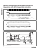
UPDATE
FCR
0.25s TO 16s
UPDATE
TEMP DATA
FAN
CONVERSION
RATE
TACH IN
FAN-SPEED
CONTROL
(FSC)
FAN
THRESHOLD
TEMPERATURE
(T
FAN
)
TEMPERATURE
CONVERTER
REMOTE
SENSOR
Figure 6. MAX6661 Thermal Loop