
User guide


MAX6661
Remote Temperature-Controlled Fan-Speed
Regulator with SPI-Compatible Interface
______________________________________________________________________________________ 15
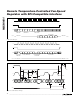
REGISTER/ADDRESS FS (BFH = READ, C0H = WRITE)
COMMAND READ/WRITE MAXIMUM TEMPERATURE LIMIT BYTE
Label
7
MSB
6
Data Bit
5
Data Bit
4
Data Bit
3
Data Bit
2
Data Bit
1
Data Bit
0
Data Bit
POR State 11111111
Table 9. Fan Full-Scale Register (RFS/WFS)
Note: This register determines the maximum reference frequency at the input of the up/down counter. It controls a programmable
divider that can be set anywhere between 127 and 255. The value in this register must be set in accordance with the procedure
described in the TACH IN section (equivalent 8415/(Max Tachometer Frequency
✕ Fan Tachometer Divisor)). Programmed value
below 127 defaults to 127. POR value is 255.
REGISTER/ADDRESS FTD (BBH = READ, BCH = WRITE)
COMMAND READ LIMIT/FAILURE REGISTER
Label
7
Not Used
6
Not Used
5
Not Used
4
Not Used
3
Not Used
2
Not Used
1
Divisor
Bit 1
0
Divisor
Bit 0
POR State 0 0 000001
Table 10. Fan Tachometer Divisor Register (RFTD/WFTD)
Note: This byte sets the prescalar division ratio for tachometer or current-sense feedback. (This register does not apply to the tach
signal used in the fan-speed register.) Select this value such that the fan frequency (rpm / 60s x number of poles) divided by the
FCD falls in the 33Hz to 66Hz range. See TACH IN section:
Bits 1, 0: 00 = divide by 1, 01 = divide by 2, 10 = divide by 4, 11 = divide by 8.
REGISTER/ADDRESS FSC (ABH = READ, B4H = WRITE)
COMMAND READ/WRITE FAN DAC REGISTER
Label
7
Not Used
6
Overflow Bit
5
(MSB)
4
Data
3
Data
2
Data
1
Data
0
Data
POR State 0 0 0 0 0 0 0 0
Table 7. Fan Speed Control Register (RFSC/WFSC)
REGISTER/ADDRESS FG (ADH = READ, B6H = WRITE)
COMMAND READ/WRITE FAN GAIN REGISTER
Label
7
Always
Write
a 1
6
Fan
Gain
5
Fan Gain
4
Always
Write
a 0
3
Always
Write
a 0
2
Always
Write
a 0
1
Fan
Driver
Mode Bit
0
Fan
Feedback
Mode
POR State 1 0 0 0 0 0 0 0
Table 8. Fan Gain Register (RFG/WFG)
Notes: Bit 0: Fan driver mode. When bit 0 is set to 1, the fan driver is in fan open-loop mode. In this mode, the fan DAC programs the
fan voltage rather than the fan speed. Tachometer feedback is ignored, and the user must consider minimum fan drive and startup
issues. Thermal open loop is automatically set to 1 (see configuration register). Fan Fail (bit 0 of the status register) is set to 1 in this
mode and should be ignored.
Bit 1: Fan feedback mode. When bit 1 is set to 1, the fan loop uses driver current sense rather than tachometer feedback.
Bits 6, 5: Fan gain of the fan loop, where 00 = 8°C with resolution = 4 bits. This means that the fan reaches its full-scale (maximum)
speed when there is an 8°C difference between the remote-diode temperature and the value stored in T
FAN
, 01 = +16°C, with a 5-bit
resolution and 10 = +32°C with a 6-bit resolution.
Bit 7: Writing a zero to bit 7 forces bits 6 and 5 to their POR values.