
User guide

MAX6661
Remote Temperature-Controlled Fan-Speed
Regulator with SPI-Compatible Interface
_______________________________________________________________________________________ 3
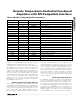
ELECTRICAL CHARACTERISTICS (continued)
(V
CC
= 3V to 5.5V, V
FAN
= 12V, T
A
= -40°C to +125°C, unless otherwise specified. Typical values are at V
CC
= 3.3V and T
A
=
+25°C.) (Notes 1 and 2)
Note 1: T
A
= T
J
. This implies zero dissipation in pass transistor (no load, or fan turned off).
Note 2: All parameters are 100% production tested at a single temperature, unless otherwise indicated. Parameter values through
temperature are guaranteed by design.
Note 3: The fan control section of the MAX6661 and temperature comparisons use only 9 bits of the 11-bit temperature measure-
ment with a 0.5°C LSB.
Note 4: Wide-range accuracy is guaranteed by design, not production tested.
Note 5: Guaranteed by design.
PARAMETER SYMBOL CONDITIONS MIN TYP MAX UNITS
INTERFACE PINS (SDIN, SC, CS, DOUT, ALERT, OVERT)
Serial Bus Maximum Clock
Frequency (Note 5)
SC 2.5 MHz
V
CC
= 3V 2.2
Logic Input High Voltage
V
CC
= 5.5V 2.4
V
Logic Input Low Voltage V
CC
= 3V to 5V 0.8 V
Logic Output High-Voltage
DOUT
V
CC
= 3V, I
SOURCE
= 6mA (Note 5)
V
CC
-
0.4V
V
Logic Output Low-Voltage DOUT V
CC
= 3V, I
SINK
= 6mA (Note 5) 0.4 V
Logic Output Low-Voltage
ALERT, OVERT
V
CC
= 3V, I
SINK
= 6mA (Note 5) 0.4 V
ALERT, OVERT Output
High Leakage Current
ALERT, OVERT forced to 5.5V 1 µA
Logic Input Current Logic inputs forced to V
CC
or GND -2 2 µA
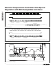
SPI AC TIMING (Figure 5)
CS High to DOUT Three-State t
TR
C
LOAD
= 100pF, R
GS
= 10kΩ (Note 5) 200 ns
CS to SC Setup Time t
CSS
(Note 5) 200 ns
SC Fall to DOUT Valid t
DO
C
LOAD
= 100pF 200 ns
DIN to SC Setup Time t
DS
200 ns
DIN to SC Hold Time t
DH
(Note 5) 200 ns
SC Period t
CP
400 ns
SC High Time t
CH
200 ns
SC Low Time t
CL
200 ns
CS High Pulse Width t
CSW
(Note 5) 400 ns
Output Rise Time t
R
C
LOAD
= 100pF 10 ns
Output Fall Time t
F
C
LOAD
= 100pF 10 ns
SC Falling Edge to CS Rising
t
SCS
(Note 5) 200 ns