
User guide

Detailed Description
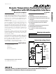
The MAX6661 is a remote temperature sensor and fan
controller with an SPI interface. The MAX6661 converts
the temperature of a remote PN junction to a 10-bit +
sign digital word. The remote PN junction can be a
diode-connected transistor, such as a 2N3906, or the
type normally found on the substrate of many proces-
sors’ ICs. The temperature information is provided to the
fan-speed regulator and is read over the SPI interface.
The temperature data, through the SPI interface, can be
read as a 10-bit + sign two’s complement word with a
0.125°C resolution (LSB) and is updated every 0.5s.
The MAX6661 incorporates a closed-loop fan controller
that regulates the fan speed with tachometer feedback.
The temperature information is compared to a threshold
and range setting, which enables the MAX6661 to auto-
matically set fan speed proportional to temperature.
Full control of the fan is available by being able to open
either the thermal control loop or the fan control loop.
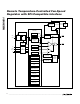
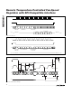
Figure 1 shows a simplified block diagram.
ADC
The ADC is an averaging type that integrates the signal
input over a 125ms period with excellent noise rejec-
tion. A bias current is steered through the remote
diode, where the forward voltage is measured, and the
temperature is computed. The DXN pin is the cathode
of the remote diode and is biased at 0.7V above
ground by an internal diode to set up the ADC inputs
for a differential measurement. The worst-case DXP-
DXN differential input voltage range is 0.25V to 0.95V.
Excess resistance in series with the remote diode caus-
es about 1/2°C error per ohm. Likewise, 200mV of off-
set voltage forced on DXP-DXN causes approximately
1°C error.
A/D Conversion Sequence
A temperature-conversion sequence is initiated every
500ms in the free-running autoconvert mode (bit 6 = 0
in the configuration register) or immediately by writing a
one-shot command. The result of the new measurement
is available after the end of conversion. The results of
the previous conversion sequence are still available
when the ADC is converting.
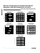
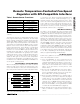
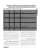
Remote-Diode Selection
Temperature accuracy depends on having a good-
quality, diode-connected, small-signal transistor.
Accuracy has been experimentally verified for all
devices listed in Table 1. The MAX6661 can also direct-
ly measure the die temperature of CPUs and other ICs
that have on-board temperature-sensing diodes.
MAX6661
Remote Temperature-Controlled Fan-Speed
Regulator with SPI-Compatible Interface
_______________________________________________________________________________________ 5
Pin Description
PIN NAME FUNCTION
1V
FAN
Power Supply for Fan Drive: 4.5V to 13.5V
2V
CC
Power Supply: 3V to 5.5V. Bypass with a 0.1µF capacitor to GND.
3 DXP Input: Remote-Junction Anode. Place a 2200pF capacitor between DXP and DXN for noise filtering.
4 DXN Input: Remote-Junction Cathode. DXN is internally biased to a diode voltage above ground.
5 FAN Output to Fan Low Side
6 N.C. No External Connection. Must be left floating.
7 PGND Power Ground
8 AGND Analog Ground
9 OVERT Output to System Shutdown. Active-low output, programmable for active high, if desired. Open drain.
10 CS SPI Chip Select. Active low.
11 ALERT Open-Drain Active-Low Output
12 DOUT SPI Data Output. High-Z when not being read.
13 GAIN
Leave open if tachometer feedback is being used. Connect an external resistor to V
CC
to reduce the
gain of the current sense.
14 SCL SPI Clock
15 SDIN SPI Data In
16 TACH IN Fan Tachometer Input. 13.5V tolerant, pullup from V
CC
to 13.5V is allowed on this line.