
User guide
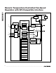

register is not loaded. DOUT is high impedance during
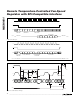
a WRITE operation. Figure 4 shows the write cycle.
For single byte commands such as OSHT and SPOR,
the operation need only be 7 bits long where the
READ/WRITE bit is omitted. Here the command is
loaded into the shift register on the rising edge of SC
and the command is decoded during the high period of
the 7th clock pulse. The 7th falling edge of SC shifts the
command from the shift register to the appropriate reg-
ister. CS can then go high after the SC low to CS high
hold time t
CSH
(see SPI AC Timing, Electrical Char-
acteristics). Figure 5 shows the timing waveforms for
the MAX6661’s SPI interface.
Remote Temperature Data Register
Two registers, at addresses 81h and 83h, store the
measured temperature data from the remote diode. The
data format for the remote-diode temperature is 10 bits
+ sign, with each LSB corresponding to 0.125°C, in
two’s complement format (Table 3). Register 83h con-
tains the sign bit and the first 7 bits. Bits 7, 6, and 5 of
register 81h are the 3LSBs. If the two registers are not
read immediately, one after the other, their contents
may be the result of two different temperature measure-
ments, leading to erroneous temperature data. For this
reason, a parity bit has been added to the 81h register.
Bit 4 of this is zero if the data in 81h and 83h are from
the same temperature conversion and 83h is read first.
Otherwise, bit 4 is one. The remaining bits are don’t
cares. When reading temperature data, register 83h
must be read first.
Alarm Threshold Registers
The MAX6661 provides four alarm threshold registers
that can be programmed with a two’s complement tem-
perature value with each LSB corresponding to 1°C.
The registers are T
HIGH
, T
LOW
, T
MAX
, and T
HYST
. If the
measured temperature equals or exceeds T
HIGH
, or is
less than T
LOW
, an ALERT interrupt is asserted. If the
measured temperature equals or exceeds T
MAX
, the
OVERT output is asserted (see the Overtemperature
Output
OVERT
section). The POR state for T
HIGH
is
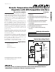
MAX6661
Remote Temperature-Controlled Fan-Speed
Regulator with SPI-Compatible Interface
_______________________________________________________________________________________ 9
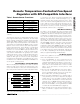
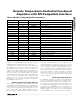
REGISTERS COMMAND POR STATE FUNCTION
RRL 81h 00000000 Read Remote Temperature Low Byte (3MSBs)
RRH 83h 00000000 Read Remote Temperature High Byte (Sign Bit and First 7 Bits)
RSL 85h 00000000 Read Status Byte
RCL/WCL 87h/92h 00000000 Read/Write Configuration Byte
RFCR/WFCR 89h/94h 00000010 Read/Write Fan-Conversion Rate Byte
RTMAX/WTMAX A1h/A4h 01100100 (+100°C) Read/Write Remote T
MAX
RTHYST/WTHYST A3h/A6h 01011111 (+95°C) Read/Write Remote T
HYST
RTHIGH/WTHIGH 8Fh/9Ah 01111111 (+127°C) Read/Write Remote T
HIGH
RTLOW/WTLOW 91h/9Ch 11001001 (-55°C) Read/Write Remote T
LOW
SPOR F8h N/A Write Software POR
OSHT 9Eh N/A Write One-Shot Temperature Conversion
RTFAN/WTFAN A9h/B2h 00111100 (+60°C) Read/Write Fan-Control Threshold Temperature T
FAN
RFSC/WFSC ABh/B4h 00000000 Read/Write Fan-Speed Control
RFG/WFG ADh/B6h 10000000 Read/Write Fan Gain
RFTP AFh 00000000 Read Fan Tachometer Period
RFTCL/WFTPLP B1h/B8h 11111111 Read/Write Fan Tachometer Period Limit (Fan-Failure Limit)
RFTD/WFTD BBh/BCh 00000001 Read/Write Fan Tachometer Divisor
RFS/WFS BFh/C0h 11111111 Read/Write Full-Scale Register
RM/WM F5h/F6h 00000000 Read/Write Mode Register
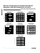
ID CODE FDh 01001101 Read Manufacturer ID Code
ID CODE FFh 00001001 Read Device ID Code
Table 2. MAX6661 Command-Byte Bit Assignments