
Instruction Manual


MAX6662
12-Bit + Sign Temperature Sensor with
SPI-Compatible Serial Interface
4 _______________________________________________________________________________________
0
4
2
8
6
10
12
-50 500 100 150
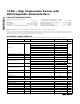
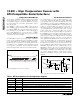
SHUTDOWN CURRENT
VS. TEMPERATURE
MAX6662 toc04
TEMPERATURE (°C)
SHUTDOWN CURRENT (µA)
V
CC
= +5.0V
V
CC
= +3.0V
V
CC
= +3.3V
Typical Operating Characteristics (continued)
(V
CC
= +3V, T
A
= +25°C, unless otherwise noted.)
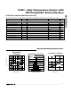
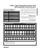
Pin Description
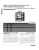
Detailed Description
The MAX6662 continuously converts its die tempera-
ture into a digital value using its integrated ADC.
Temperature data is updated twice a second. The
resulting data is readable at any time through the SPI-
compatible serial interface.
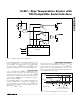
Figure 1 shows the simplified functional diagram of the
MAX6662. Its internal current sources force 100µA and
10µA currents through a diode (diode-connected tran-
sistor), while the integrating ADC measures the voltage
difference. The difference in voltage corresponds to the
die temperature. The result is stored in the Temperature
register. The control logic unit compares the tempera-
ture and the temperature limit settings stored in the reg-
isters to determine whether a fault condition has
occurred.
Temperature Fault Alert
The ALERT is an open-drain active-low (default, also
programmable active-high) output used to alert the sys-
tem to temperature faults. ALERT can be programmed
to operate in either one of two modes: comparator or
interrupt mode.
Interrupt Mode
In the interrupt mode, the MAX6662 ALERT pin asserts
an alarm for an undertemperature (T
LOW
) fault, as well
as for an overtemperature (T
HIGH
) fault. Once either
fault has occurred, it remains active indefinitely, regard-
less of condition. ALERT is unconditionally deasserted
(even if Temperature is still out of limits) by reading the
temperature register. ALERT only asserts again if the
temperature crosses the hysteresis, thereby corre-
sponding to the fault (T
LOW
or T
HIGH
) that initially set
the ALERT.
PIN NAME FUNCTION
1 SCLK Serial-Clock Input
2 CS Chip Select Input. Set low to enable the serial interface for data input/output.
3 SIO Serial-Data Input/Output. Bidirectional data input and output for serial interface.
4 GND Ground
5 OT Overtemperature Output. Open-drain output requires a pullup resistor to V
CC
.
6 ALERT Alert Output. Open-drain output requires a pullup resistor to V
CC
.
7 NC No Connection. Do not make a connection to this pin.
8V
CC
Supply Voltage Input. Bypass to GND with a 0.1µF capacitor as close to V
CC
as possible.