
User guide

MAX6665
Fan Controller/Driver with Factory-
Programmed Temperature Thresholds
4 _______________________________________________________________________________________
Detailed Description
The MAX6665 is a simple fan controller/driver that turns
on the internal power transistor when its die tempera-
ture exceeds a factory-set threshold. By connecting a
small (typically 5V to 12V, 100mA to 250mA) cooling
fan to FANOUT, a simple on/off fan-control system is
created. FANOUT drives the fan’s low side. The fan’s
positive supply pin should be connected to its normal
power-supply voltage (up to 24V nominal).
To turn the fan on when the MAX6665’s die temperature
is less than the threshold voltage, drive FORCEON low.
This overrides the internal control circuitry and allows
an external device to activate the fan. FANON is an
active-high push-pull logic output that goes high when
the fan is turned on, either when temperature exceeds
the threshold or the fan is forced on.
WARN is an active-low, open-drain digital output that
indicates the MAX6665’s die temperature exceeds
15°C above the fan trip threshold. WARN output serves
as a warning that the system temperature has contin-
ued to rise well above the fan activation temperature.
OT is an active-low open-drain digital output that indi-
cates the MAX6665’s die temperature exceeds 30°C
above the fan trip threshold. It serves as a thermal shut-
down output to the system in case of excessive temper-
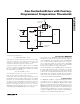
ature rise. Figure 1 shows a typical application circuit
for a high-reliability, fail-safe temperature monitor.
Applications Information
Thermal Considerations and Hysteresis
The temperature comparator has hysteresis to prevent
small temperature changes near the threshold temper-
ature from causing the fan to turn on and off repeatedly
over short periods of time. The FANOUT pin goes
active and powers the fan when the MAX6665’s die
temperature exceeds the factory-programmed trip tem-
perature. As the cooling fan operates, the circuit board
temperature should decrease, which in turn causes the
MAX6665’s die temperature to decrease. When the die
temperature is equal to the trip threshold minus the
hysteresis, the FANOUT pin turns the fan off, removing
power from the fan. The HYST pin sets the amount of
hysteresis to 1°C, 4°C, or 8°C by letting the pin float or
connecting to GND or V
DD
, respectively. This allows
the amount of hysteresis to be matched to the cooling
and noise requirements of the system.
Hysteresis is also affected by self-heating of the
MAX6665’s die. The fan current flowing through the on-
chip power transistor causes the die temperature to
increase. For example, assume the MAX6665 controls
a 125mA fan. When the fan is operating, the voltage
drop across the output transistor is typically under
250mV. At 250mV, the power dissipation is 31.25mW.
The thermal resistance of the MAX6665 package (with
EP soldered) is 51°C/W, so the die temperature
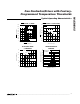
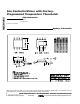
PIN NAME FUNCTION
1 GND Ground
2 FORCEON
Force Fan On Input. Set FORCEON low to force the fan switch on. Set FORCEON high for normal
operation.
3 HYST
Three-State Hysteresis Input. Connect HYST to V
DD
for 8°C, GND for 4°C, and leave HYST
unconnected for 1°C hysteresis.
4 FANON
Fan-On Indicator Output. Push-pull output. FANON is high when the fan switch is on. FANON is low
when the fan switch is off.
5 OT
Overtemperature Output. Active-low when the temperature is 30°C above the fan threshold. Open-
drain output, requires resistive pullup.
6 WARN
Overtemperature Warning Output. Active-low when the temperature is 15°C above the fan
threshold. Open-drain output, requires resistive pullup.
7V
DD
Supply Voltage. Bypass with a 1µF capacitor to GND as close to V
DD
pin as possible.
8 FANOUT Fan-Switch (Driver) Output. Connect to the low side of a fan.
Exposed
Paddle
GND
Ground
Pin Description