
User guide

increases by a maximum of:
51°C/W x 0.03125W = 1.59°C
Therefore, the effective hysteresis is about 1.59°C high-
er than the hysteresis selected by the HYST pin. For
example, setting the HYST pin for 8°C of hysteresis
results in an effective hysteresis of about 9.6°C.
A larger fan with a power-supply current of 250mA
causes a maximum voltage drop of 0.6V at the output
pin. This results in 150mW power dissipation and the
die temperature increases by:
51°C/W x 0.150W = 7.65°C
If the HYST pin has been set for 8°C of hysteresis, the
total effective hysteresis will be about 15.7°C.
Using fans with somewhat higher operating current
than 250mA results in higher voltage across the output
transistor. The increased power dissipation caused by
the higher current and voltage levels will increase self-
heating, thereby increasing the effective hysteresis.
When using higher-power fans, be sure that the
MAX6665’s power dissipation does not cause so much
self-heating that the MAX6665 stays on constantly.
Locating the MAX6665
The location of the MAX6665 in the system affects its
operation. Because the fan is turned on and off based
on the MAX6665’s die temperature, place the MAX6665
close to major heat-generating components in the sys-
tem—a high-speed CPU or a power device, for exam-
ple. A higher supply voltage reduces the FANOUT
voltage, which reduces the self-heating effects.
The die temperature of the MAX6665 tracks the tempera-
ture of its leads and the EP. If it is soldered to a PC board,
it quickly reaches the temperature of the traces in that
section of the circuit board. Air temperature affects the die
temperature. Since the plastic package does not conduct
heat as well as the leads, the effect of air temperature is
much less than that of lead temperature.
Layout Issues
The MAX6665’s GND pin is ground return for the fan dri-
ver and the device. Large fan current induces noise
(ground bounce) to the MAX6665. Bypass V
DD
to GND
with a 1µF tantalum capacitor located as close to the
MAX6665 as possible. For long V
DD
and GND lines, an
additional bypass capacitor may be needed. The bypass
capacitor reduces GND noise. The EP is internally con-
nected to the GND pin. Solder the EP to the ground plane
for better electrical and thermal performance.
MAX6665
Fan Controller/Driver with Factory-
Programmed Temperature Thresholds
_______________________________________________________________________________________ 5
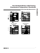
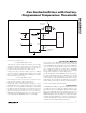
Figure 1. High-Reliability, Fail-Safe Fan Controller and Temperature Monitor
V
DD
FANON
GND
HYST
V
DD
+3.3V
+4.5V TO +24V
100mA TO 250mA
COOLING FAN
100kΩ
1µF
µP
I/O
I/O
SYSTEM POWER
SHUTDOWN
MAX6665
FORCEON
FANOUT
WARN
OT
V
DD
100kΩ