
User guide

MAX6678
Duty-Cycle Rate-of-Change Control
To reduce the audibility of changes in fan speed, the
rate of change of the duty cycle is limited by the values
set in the duty-cycle rate-of-change register. Whenever
the target duty cycle is different from the instantaneous
duty cycle, the duty cycle increases or decreases at
the rate determined by the duty-cycle rate-of-change
byte until it reaches the target duty cycle. By setting the
rate of change to the appropriate value, the thermal
requirements of the system can be balanced against
good acoustic performance. Slower rates of change are
less noticeable to the user, while faster rates of change
can help minimize temperature variations. Remember
that the fan controller is part of a complex control sys-
tem. Because several of the parameters are generally
not known, some experimentation may be necessary to
arrive at the best settings.
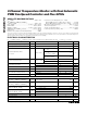
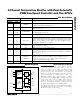
Power-Up Defaults
At power-up, or when the POR bit in the configuration
byte register is set, the MAX6678 has the default set-
tings indicated in Table 2. Some of these settings are
summarized below:
• Temperature conversions are active.
• Channel 1 and channel 2 are set to report the remote
temperature channel measurements.
• Channel 1 OT limit = +110°C.
• Channel 2 OT limit = +80°C.
• Manual fan mode.
• Fan duty cycle = 0.
• PWM invert bit = 0.
• PWMOUT_ are high.
• When using an NMOS or npn transistor, the fan starts
at full speed on power-up.
OT
Output
When temperature exceeds the OT temperature thresh-
old and OT is not masked, the OT status register indi-
cates a fault and OT output becomes active. If OT for
the respective channel is masked off, the OT status
register continues to be set, but the OT output does not
become active.
The fault flag and the output can be cleared only by
reading the OT status register and the temperature reg-
ister of that channel. If the OT status bit is cleared, OT
reasserts on the next conversion if the temperature still
exceeds the OT temperature threshold.
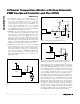
GPIO Inputs/Outputs and Presets
The MAX6678 contains five GPIO pins (GPIO0 through
GPIO4). When set as an output, the GPIO pin connects
to the drains of internal n-channel MOSFETs. When the
n-channel MOSFET is off, the pullup resistor (see the
Typical Operating Circuit) provides a logic-level high
output. When a GPIO pin is configured as an input, read
the state of GPIO_ from the GPIO value register (15h).
The MAX6678 powers up with GPIO0, GPIO1, and
GPIO2 high impedance and GPIO3 and GPIO4 pulled
low. After 2ms, the GPIOs go to their assigned preset
values. The preset values are set by connecting the
associated PRESET inputs to either GND or V
CC
. With
PRESET“N” connected to GND, GPIO“N” pulls low; with
PRESET“N” connected to V
CC
, GPIO“N” pulls high
through the pullup resistor. After power-up, the functions
and states of the GPIOs can be read and controlled
using registers 15h and 16h.
Register Descriptions
The MAX6678 contains 26 internal registers. These reg-
isters store temperature, allow control of the PWM out-
puts, determine if the MAX6678 is measuring from the
internal or remote temperature sensors, and set the
GPIO as inputs or outputs.
Temperature Registers (00h and 01h)
These registers contain the results of temperature mea-
surements. The value of the MSB is +128°C, and the
value of the LSB is +1°C. Temperature data for remote
diode 1 is in the temperature channel 1 register.
Temperature data for remote diode 2 OR the local sen-
sor (selectable by bit D1 in the configuration byte) is
stored in the temperature channel 2 register.
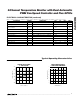
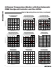
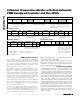
Configuration Byte (02h)
The configuration byte register controls timeout condi-
tions and various PWMOUT signals. The POR state of
the configuration byte register is 00h. See Table 3 for
configuration byte definitions.
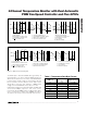
Channel 1 and Channel 2 OT Limits (03h and 04h)
Set channel 1 (03h) and channel 2 (04h) temperature
thresholds with these two registers. Once the tempera-
ture is above the threshold, the OT output is asserted low
(for the temperature channels that are not masked). The
POR state of the channel 1 OT limit register is 6Eh, and
the POR state of the channel 2 OT limit register is 50h.
2-Channel Temperature Monitor with Dual Automatic
PWM Fan-Speed Controller and Five GPIOs
10 ______________________________________________________________________________________