
User guide

MAX6678
2-Channel Temperature Monitor with Dual Automatic
PWM Fan-Speed Controller and Five GPIOs
2 _______________________________________________________________________________________
ABSOLUTE MAXIMUM RATINGS
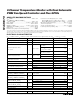
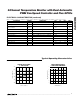
ELECTRICAL CHARACTERISTICS
(V
CC
= +3.0V to +5.5V, T
A
= -40°C to +125°C, unless otherwise noted. Typical values are at V
CC
= +3.3V, T
A
= +25°C.)
Stresses beyond those listed under “Absolute Maximum Ratings” may cause permanent damage to the device. These are stress ratings only, and functional
operation of the device at these or any other conditions beyond those indicated in the operational sections of the specifications is not implied. Exposure to
absolute maximum rating conditions for extended periods may affect device reliability.
V
CC
to GND..............................................................-0.3V to +6V
OT, SMBDATA, SMBCLK, PWMOUT_,
GPIO_ to GND ......................................................-0.3V to +6V
DXP_ to GND ..........................................-0.3V to + (V
CC
+ 0.3V)
DXN to GND ..........................................................-0.3V to +0.8V
PRESET_ to GND ....................................-0.3V to + (V
CC
+ 0.3V)
SMBDATA, OT, PWMOUT_ Current....................-1mA to +50mA
DXN Current .......................................................................±1mA
ESD Protection (all pins, Human Body Model) ..................2000V
Continuous Power Dissipation (T
A
= +70°C)
20-Pin QSOP (derate 9.1mW/°C above +70°C).......... 727mW
20-Pin TQFN (derate 34.5mW/°C above +70°C) .......2759mW
Operating Temperature Range .........................-40°C to +125°C
Junction Temperature......................................................+150°C
Storage Temperature Range ............................-65°C to +150°C
Lead Temperature (soldering, 10s) .................................+300°C
PARAMETER SYMBOL CONDITIONS MIN TYP MAX UNITS
Operating Supply Voltage Range V
CC
+3.0 +5.5 V
Operating Current I
S
Interface inactive, ADC active 0.5 1 mA
+25°C ≤ T
R
≤ +125°C,
T
A
= 60°C
±1
V
CC
= 3.3V
0°C ≤ T
R
≤ +145°C,
+25°C ≤ T
A
≤ +100°C
±3
External Temperature Error,
V
CC
= 3.3V
0°C ≤ T
R
≤ +145°C,
0°C ≤ T
A
≤ +125°C
±4
°C
+25°C ≤ T
R
≤ +100°C ±2.5
Internal Temperature Error V
CC
= +3.3V
0°C ≤ T
A
≤ +125°C ±4
°C
1°C
Temperature Resolution
8 Bits
Conversion Time 200 250 300 ms
PWM Frequency Tolerance (Note 1) -20 +20 %
High level 80 100 120
Remote-Diode Sourcing Current
Low level 8 10 12
µA
DXN Source Voltage 0.7 V
DIGITAL INPUTS AND OUTPUTS
Output Low Voltage (Sink Current)
(OT, GPIO_, SMBDATA, PWMOUT_)
V
OL
I
OUT
= 6mA 0.4 V
Output High Leakage Current
(OT, GPIO_, SMBDATA, PWMOUT_)
I
OH
1µA
V
CC
= 3V to 3.6V 0.8
Logic-Low Input Voltage (SMBDATA,
SMBCLK, PRESET_, GPIO_)
V
IL
V
CC
= 3.6V to 5.5V 0.8
V
V
CC
= 3V to 3.6V 2.1
Logic-High Input Voltage (SMBDATA,
SMBCLK, PRESET_, GPIO_)
V
IH
V
CC
= 3.6V to 5.5V 2.1
V
Input Leakage Current 1µA
Input Capacitance C
IN
5pF
SMBus TIMING
Serial Clock Frequency f
SCLK
100 kHz