
User guide

Detailed Description
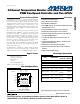
The MAX6678 temperature sensor and fan controller
accurately measures the temperature of either two
remote pn junctions or one remote pn junction and its
own die. The device reports temperature values in digi-
tal form using a 2-wire serial interface. The remote pn
junction is typically the emitter-base junction of a com-
mon-collector pnp on a CPU, FPGA, or ASIC. The
MAX6678 operates from supply voltages of 3.0V to
5.5V and consumes 500µA (typ) of supply current. The
temperature data controls a PWM output signal to
adjust the speed of a cooling fan. The device also fea-
tures an overtemperature alarm output to generate
interrupts, throttle signals, or shutdown signals.
Five GPIO input/outputs provide additional flexibility.
The GPIO power-up states are set by connecting the
GPIO preset inputs to ground or V
CC
.
MAX6678
2-Channel Temperature Monitor with Dual Automatic
PWM Fan-Speed Controller and Five GPIOs
_______________________________________________________________________________________ 5
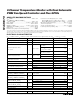
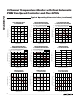
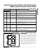
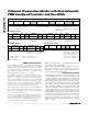
Pin Description
PIN
THIN QFN QSOP
NAME DESCRIPTION
13 SMBDATA
SMBus Serial-Data Input/Output, Open Drain. Can be pulled up to 5.5V,
regardless of V
CC
. Open circuit when V
CC
= 0.
24 SMBCLK
SMBus Serial-Clock Input. Can be pulled up to 5.5V, regardless of V
CC
. Open
circuit when V
CC
= 0.
3, 12, 13,
14, 16
5, 14, 15,
16, 18
GPIO0–GPIO4
Active-Low, Open-Drain GPIO Pins. Can be pulled up to 5.5V, regardless of
V
CC
. Open circuit when V
CC
= 0.
4, 9, 10,
11, 20
2, 6, 11,
12, 13
PRESET0–PRESET4 GPIO Preset Inputs. Connect to GND or V
CC
to set POR value of GPIO0–GPIO4.
5, 7 7, 9 DXP1, DXP2
Combined Current Source and A/D Positive Input for Remote Diode. Connect to
anode of remote-diode-connected temperature-sensing transistor. Do not leave
floating; connect to DXN if no remote diode is used. Place a 2200pF capacitor
between DXP_ and DXN for noise filtering.
68 DXN
Combined Remote-Diode Cathode Input. Connect cathode of the remote-diode-
connected transistor to DXN.
810 GND Ground. Connect to a clean ground reference.
15 17 OT
Active-Low, Open-Drain Over-Temperature Output. Typically used for system
shutdown or clock throttling. Can be pulled up to 5.5V regardless of V
CC
. Open
circuit when V
CC
= 0.
17, 19 1, 19
PWMOUT1,
PWMOUT2
Open-Drain Output to Power Transistor Driving Fan. Connect to the gate of a
MOSFET or base of a transistor. PWMOUT_ requires a pullup resistor. The
pullup resistor can be connected to a supply voltage as high as 5.5V,
regardless of the MAX6678’s supply voltage.
18 20 V
CC
Power-Supply Input. 3.3V nominal. Bypass V
CC
to GND with 0.1µF capacitor.
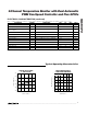
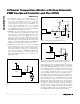
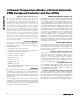
TEMPERATURE
PROCESSING
BLOCK
PWM
GENERATOR
BLOCK
SMBus
INTERFACE
AND
REGISTERS
LOGIC
MAX6678
GND
V
CC
SMBCLK
SMBDATA
DXN
DXP1
DXP2
PWMOUT1
PWMOUT2
OT
GPIO0
GPIO4
PRESET0
PRESET4
Block Diagram