
User guide

MAX6678
SMBus Digital Interface
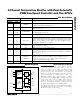
From a software perspective, the MAX6678 appears as a
set of byte-wide registers. This device uses a standard
SMBus 2-wire/I
2
C™-compatible serial interface to access
the internal registers. The MAX6678 has four different
slave addresses available; therefore, a maximum of four
MAX6678 devices can share the same bus.
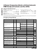
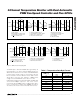
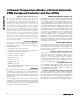
The MAX6678 employs four standard SMBus protocols:
write byte, read byte, send byte, and receive byte
(Figures 1, 2, and 3). The shorter receive byte protocol
allows quicker transfers, provided that the correct data
register was previously selected by a read byte instruc-
tion. Use caution with the shorter protocols in multimaster
systems, since a second master could overwrite the
command byte without informing the first master.
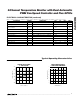
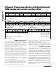
Temperature data can be read from registers 00h and
01h. The temperature data format for these registers is
8 bits, with the LSB representing 1°C (Table 1) and the
MSB representing +128°C. The MSB is transmitted first.
All values below 0°C clip to 00h.
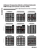
Table 2 details the register address and function, whether
they can be read or written to, and the power-on reset
(POR) state. See Tables 2–6 for all other register functions
and the Register Descriptions section.
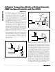
Temperature Reading
The MAX6678 contains two external temperature mea-
surement inputs to measure the die temperature of CPUs
or other ICs having on-chip temperature-sensing diodes,
or discrete diode-connected transistors as shown in the
Typical Operating Circuits. For best accuracy, the dis-
crete diode-connected transistor should be a small-signal
device with its collector and base connected together.
The on-chip ADC converts the sensed temperature and
outputs the temperature data in the format shown in Table
1. Temperature channel 2 can be used to measure either
a remote thermal diode or the internal temperature of the
MAX6678. Bit D1 of register 02h (Table 2) selects local or
remote sensing for temperature channel 2 (1 = local). The
temperature measurement resolution is 1°C for both local
and remote temperatures. The temperature accuracy is
within ±1°C for remote temperature measurements from
+60°C to +100°C.
2-Channel Temperature Monitor with Dual Automatic
PWM Fan-Speed Controller and Five GPIOs
6 _______________________________________________________________________________________
Write Byte Format
Read Byte Format
Send Byte Format
Receive Byte Format
Slave address: equiva-
lent to chip-select line of
a 3-wire interface
Command byte: selects which
register you are writing to
Data byte: data goes into the register
set by the command byte (to set
thresholds, configuration masks, and
sampling rate)
Slave address: equivalent
to chip-select line
Command byte: selects
which register you are
reading from
Slave address: repeated
due to change in data-
flow direction
Data byte: reads from
the register set by the
command byte
Command byte: sends com-
mand with no data, usually
used for one-shot command
Data byte: reads data from
the register commanded
by the last read byte or
write byte transmission;
also used for SMBus alert
response return address
S = Start condition Shaded = Slave transmission
P = Stop condition /// = Not acknowledged
Figure 1. SMBus Protocols
S ADDRESS RD ACK DATA /// P
— 7 bits — — 8 bits — —
WRS ACK COMMAND ACK P
— — — 8 bits — —
ADDRESS
7 bits
P
1
ACK
—
DATA
8 bits
ACK
—
COMMAND
8 bits
ACK
—
WR
—
ADDRESS
7 bits
S
—
S ADDRESS WR ACK COMMAND ACK S ADDRESS
7 bits——8 bits——7 bits—
RD
—
ACK
—
DATA
8 bits
///
—
P
—
I
2
C is a trademark of Philips Corp.
Purchase of I
2
C components from Maxim Integrated Products,
Inc., or one of its sublicensed Associated Companies, conveys
a license under the Philips I
2
C Patent Rights to use these com-
ponents in an I
2
C system, provided that the system conforms
to the I
2
C Standard Specification as defined by Philips.