
User guide

The duty cycle of the PWM can be controlled in two ways:
1) Manual PWM control by setting the duty cycle of the
fan directly through the fan target duty-cycle regis-
ters (0Bh and 0Ch).
2) Automatic PWM control by setting the duty cycle
based on temperature.
Manual PWM Duty-Cycle Control
Clearing the bits that select the temperature channels for
fan control (D5 and D4 for PWMOUT1 and D3 and D2 for
PWMOUT2) in the fan-configuration register (11h)
enables manual fan control. In this mode, the duty cycle
written to the fan target duty-cycle register directly con-
trols the corresponding fan. The value is clipped to a
maximum of 240. Any value entered above that is
changed to 240 automatically. In this control mode, the
value in the maximum duty-cycle register is ignored and
does not affect the duty cycle used to control the fan.
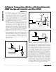
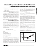
Automatic PWM Duty-Cycle Control
In the automatic control mode, the duty cycle is con-
trolled by the local or remote temperature according to
the settings in the control registers. Below the fan-start
temperature, the duty cycle is either 0% or is equal to
the fan-start duty cycle, depending on the value of bit
D3 in the configuration byte register. Above the fan-
start temperature, the duty cycle increases by one duty
cycle step each time the temperature increases by one
temperature step. The target duty cycle is calculated
based on the following formula; for temperature >
FanStartTemperature:
where:
DC = DutyCycle
FSDC = FanStartDutyCycle
T = Temperature
FST = FanStartTemperature
DCSS = DutyCycleStepSize
TS = TempStep
Duty cycle is recalculated after each temperature con-
version if temperature is increasing. If the temperature
begins to decrease, the duty cycle is not recalculated
until the temperature drops by 5°C from the last peak
temperature. The duty cycle remains the same until the
temperature drops 5°C from the last peak temperature or
the temperature rises above the last peak temperature.
For example, if the temperature goes up to +85°C and
starts decreasing, duty cycle is not recalculated until the
temperature reaches +80°C or the temperature rises
above +85°C. If the temperature decreases further, the
duty cycle is not updated until it reaches +75°C.
For temperature < FanStartTemperature and D2 of
configuration register = 0:
DutyCycle = 0
For temperature < FanStartTemperature and D2 of
configuration register = 1:
DutyCycle = FanStartDutyCycle
Once the temperature crosses the fan-start tempera-
ture threshold, the temperature has to drop below the
fan-start temperature threshold minus the hysteresis
before the duty cycle returns to either 0% or the fan-
start duty cycle. The value of the hysteresis is set by D7
of the fan-configuration register.
The duty cycle is limited to the value in the fan maximum
duty-cycle register. If the duty-cycle value is larger than
the maximum fan duty cycle, it is set to the maximum
fan-duty cycle as in the fan maximum duty-cycle register.
The temperature step is bit D6 of the fan-configuration
register (0Dh).
Notice if temperature crosses FanStartTemperature
going up with an initial DutyCycle of zero, a spin-up of
2s applies before the duty-cycle calculation controls
the value of the fan’s duty cycle.
FanStartTemperature for a particular channel follows the
channel, not the fan. When a fan switches channels, the
start temperature also changes to that of the new channel.
If DutyCycle is an odd number, it is automatically
rounded down to the closest even number.
DC FSDC T FST
DCSS
TS
=+ × ( ) -
MAX6678
2-Channel Temperature Monitor with Dual Automatic
PWM Fan-Speed Controller and Five GPIOs
_______________________________________________________________________________________ 9
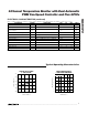
FAN-START
DUTY CYCLE
TEMPERATURE
DUTY CYCLE
REGISTER 02h,
BIT D3 = 1
DUTY-CYCLE
STEP SIZE
FAN-START
TEMPERATURE
TEMP
STEP
REGISTER 02h,
BIT D3 = 0
Figure 7. Automatic PWM Duty Control