
User Manual

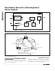
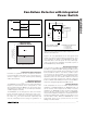

MAX6684
Fan-Failure Detector with Integrated
Power Switch
2 _______________________________________________________________________________________
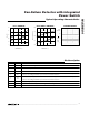
ABSOLUTE MAXIMUM RATINGS
ELECTRICAL CHARACTERISTICS
(V
CC
= 3.0 to 5.5V, OFF = V
CC
, T
A
= -40°C to +85°C, unless otherwise noted. Typical values are at V
CC
= 3.3V, T
A
= +25°C.) (Note 1)
Stresses beyond those listed under “Absolute Maximum Ratings” may cause permanent damage to the device. These are stress ratings only, and functional
operation of the device at these or any other conditions beyond those indicated in the operational sections of the specifications is not implied. Exposure to
absolute maximum rating conditions for extended periods may affect device reliability.
Note 1: Specifications to -40°C are guaranteed by design and not production tested.
Note 2: The MAX6684 is guaranteed to register a fault when the fan current fluctuates less than the minimum; it is guaranteed not to
register a fault when the fan current is above the maximum.
Voltages Referenced to GND, Unless Otherwise Noted
V
CC
........................................................................-0.3V to +6.0V
FC+, FC-.....................................................-0.3V to (V
CC
+ 0.3V)
OFF, FAIL ..............................................................-0.3V to +6.0V
PGND ....................................................................-0.3V to +0.3V
SENSE to PGND ..................................................-0.3V to +28.0V
SENSE Current................................................................1400mA
Continuous Power Dissipation (T
A
= +70°C)
8-Pin SO (derate 5.9mW/°C above +70°C)..................470mW
Operating Temperature Range ...........................-40°C to +85°C
Storage Temperature Range .............................-65°C to +150°C
Junction Temperature......................................................+150°C
Soldering Temperature (vapor phase, 60s).....................+215°C
Soldering Temperature (infrared, 15s).............................+220°C
PARAMETER SYMBOL CONDITIONS MIN TYP MAX UNITS
Supply Voltage V
CC
3.0 5.5 V
Supply Current I
CC
I
FAN
= 300mA 3.4 mA
V
CC
Shutdown Supply Current I
SHDN
OFF = GND 10 µA
SENSE-to-PGND Output
Low Voltage
I
FAN
= 300mA 0.3 0.66 V
SENSE-to-PGND Output
On-Resistance
R
DSON
1 2.2 Ω
SENSE Leakage Current V
SENSE
= 26V 1 10 µA
V
FAIL
Output Low Voltage I
FAIL
= 3mA 0.8 V
V
FAIL
Output Leakage Current V
FAIL
= 5.5V 0.1 1 µA
Average SENSE (Fan) Current 50 300
mA
SENSE Current Shutdown V
CC
= 3V 600 1200 mA
Thermal Shutdown of SENSE 15°C hysteresis 160 °C
Fan-Current Fluctuation
Frequency
No fault detected 25 400 Hz
V
FAIL
Output Delay After Fault t
FD
0.3 1 2.0 s
Minimum Fan-Current Fluctuation
Level (Note 2)
No fault detected 15 35 60 mA
P-P
OFF Input High Voltage V
IH
0.7 x
V
CC
V
OFF Input Low Voltage V
IL
0.3 x
V
CC
V
OFF Input Current -10 0 1 µA