
User Manual


MAX6684
Fan-Failure Detector with Integrated
Power Switch
_______________________________________________________________________________________ 3
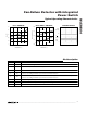
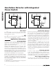
R
DSON
vs. TEMPERATURE
MAX6684 toc01
TEMPERATURE (°C)
R
DSON
(Ω)
603510-15
0.4
0.8
1.2
1.6
2.0
0
-40 85
V
CC
= 3V
I
SENSE
= 300mA
V
CC
= 5.5V
SUPPLY CURRENT vs. TEMPERATURE
MAX6684 toc02
TEMPERATURE (°C)
SUPPLY CURRENT (µA)
603510-15
225
250
275
300
200
-40 85
V
CC
= 3V
NO LOAD
V
CC
= 5.5V
OVERCURRENT OPERATION
MAX6684 toc03
20ms/div
0
0A
I
SENSE
500mA/div
V
FAIL
5V/div
V
SENSE
2V/div
0
Typical Operating Characteristics
(V
CC
= 3.3V, T
A
= +25°C, unless otherwise noted.)
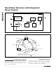
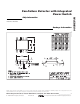
Pin Description
PIN NAME FUNCTION
1 SENSE Positive Current-Sensing Terminal. Connect SENSE to low side of fan.
2 FAIL Active-Low, Open-Drain Fan-Failure Output
3 GND Ground
4 FC-
Connect to 0.1µF capacitor for most locked-rotor detection applications. To detect minimum speed,
select C
F
according to Minimum Speed and Locked-Rotor Detection.
5 FC+
Connect to 0.1µF capacitor for most locked-rotor detection applications. To detect minimum speed,
select C
F
according to Minimum Speed and Locked-Rotor Detection.
6V
CC
Supply Voltage Input. Bypass V
CC
to GND with a 1µF capacitor.
7 OFF Acti ve- Low Fan- C ontr ol Inp ut. D r i ve O FF hi g h or l eave fl oati ng to tur n fan on. D r i ve O FF l ow to tur n fan off.
8 PGND Power Ground. Connect to GND.