
User Manual


Undercurrent (AC Component)
Fan failure is signaled if the AC component of I
FAN
is
less than 35mA
P-P
and remains out of specification for
at least 1s (Figure 2). The fan remains powered during
undercurrent failures.
Minimum Speed and
Locked-Rotor Detection
The MAX6684 asserts FAIL if the fan-current fluctuation
frequency is below 25Hz, which corresponds to a fan
speed of approximately 700rpm. The fan remains pow-
ered during a locked rotor or an under-speed failure
condition (Figures 3 and 4).
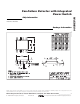
The MAX6684 can be designed to detect fan failure
below intended speeds by varying the value of C
F
.
Because of the complexity of fan-current waveforms,
the value of C
F
has to be arrived at empirically and
must be verified by bench testing. The guidelines of
Figure 5 are only appropriate for the test signals used
and do not represent all possible fan waveforms. They
are to illustrate the ability of the MAX6684 to discrimi-
nate failure due to low fan speed. As a rule, failure typi-
cally occurs when the amplitude measured at pin 4 of
the MAX6684 drops below 70mV.
Overcurrent Protection
If an overcurrent condition begins and continues for 2ms,
fan failure is signaled for 60ms. During this 60ms period,
the power to the fan is turned off. If the part does not enter
thermal shutdown and the overcurrent condition contin-
ues, power to the fan is turned on every 62ms for 2ms
(see Overcurrent Operation in Typical Operating Char-
acteristics). Once the overcurrent condition is removed,
the fan is powered continuously. A 0.1µF capacitor
between SENSE and PGND prevents the internal DMOS
switch from being damaged by back EMF current.
Thermal Shutdown
A die temperature in excess of +160°C initiates thermal
shutdown. In thermal shutdown, the MAX6684 shuts off
the fan and the FAIL output asserts. While in thermal
shutdown, the MAX6684 monitors the die temperature.
Once the die has cooled to below +145°C, the MAX6684
exits thermal shutdown and power is returned to the fan.
A thermal shutdown fault condition has precedence over
all other failure modes. While the MAX6684 die is over
temperature, power is not cycled to the fan, as occurs
during overcurrent failure.
MAX6684
Fan-Failure Detector with Integrated
Power Switch
_______________________________________________________________________________________ 5
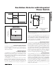
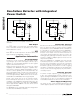
Figure 3. MAX6684 Commutation Fault Timing Diagram
FAIL
100Hz
t
FD
ƒ
Figure 4. Current Fluctuation and Commutation Frequency
Diagram
FAIL HIGH
FAIL LOW
0
10
20
30
40
50
60
70
80
0 100 200 300 400
CURRENT FLUCTUATION
vs. COMMUTATION FREQUENCY
CURRENT COMMUTATION FREQUENCY (Hz)
CURRENT FLUCTUATION
(AC COMPONENT) (mA
P-P
)
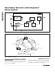
MAX6684
OFF
SENSE
APPROXIMATE FAILURE FREQUENCIES:
V
CC
FUNCTION
GENERATOR*
*35mA
P-P
SINE-WAVE AC COMPONENT
50mA TO 300mA DC COMPONENT
PGND
GND
FC+
C
F
= 0.033µF < 25Hz
C
F
= 0.01µF < 86Hz
C
F
= 0.003µF < 250Hz
10kΩ
FC-
3.3V
FAIL
C
F
Figure 5. Test Circuit Demonstrates Failure Frequency as a
Function of the Value of C
F