
User Manual

MAX746
High-Efficiency, PWM, Step-Down,
N-Channel DC-DC Controller
______________________________________________________________________________________ 11
__________________Design Procedure
Setting the Output Voltage
The MAX746’s dual-mode output voltage can be set
to 5V by grounding FB, or it can be adjusted from
2V to 14V using external resistors R4 and R5 config-
ured as shown in Figure 6. Select feedback resistor
R4 in the 10kΩ to 60kΩ range. R5 is given by:
V
OUT
R5 = (R4)
(
_______
– 1
)
2V
The MAX746 is designed to use either internal or exter-
nal feedback mode, but should not be toggled between
the two modes while operating. If two different output
voltages are required, use external feedback mode
with a resistor network similar to the 3.3V/5V adjustable
output circuit shown in Figure 7.
Selecting R
SENSE
To select the sense-resistor value (R
SENSE
), first
approximate the peak current assuming I
PK
is
(1.1) (I
LOAD
), where I
LOAD
is the maximum load cur-
rent. Once all component values have been deter-
mined, the actual peak current is given by:
V
OUT
V
OUT
I
PK
= I
LOAD
+
(
___________
)(
1–
_______
)
(2L) (f
OSC
)V
IN
V+
CP
HIGH
D2
1N914
C8
0.1µF
14
13
D3
1N914
C9
1µF
C10
0.1µF
D5
1N914
D6
1N914
15
16
D4
1N5817
C11
1µF
V
IN
CP
HIGH
14
13
16
V+
15
C8
0.1µF
D2
1N914
D3
1N914
C9
1µF
V
IN
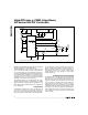
100kHz
OSCILLATOR
T FLIP-
FLOP
5V
Q
AV+
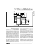
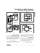
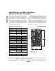
3b. CHARGE-PUMP
VOLTAGE TRIPLER
GND
GND
T
CLK
MAX746
MAX746
3a. CHARGE-PUMP
VOLTAGE DOUBLER
D4
1N5817
Figure 3. Charge-Pump Configurations
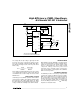
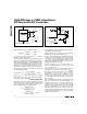
PEAK CURRENT LIMIT
vs. SOFT-START VOLTAGE
PEAK CURRENT LIMIT (A)
0
1
2
3
01234
SOFT-START VOLTAGE (V)
R
SENSE
= 50mΩ
MAX746-FG03
V+ - V
CS
= 150mV
R
SENSE
= 100mΩ
Figure 4. Peak Current Limit vs. Soft-Start Voltage
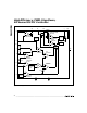
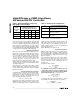
R
2
= R1 -1
GND
V+
LBO
15
1
16
…TO V
OUT
OR V
IN
V
REF
= 2.0V
R3
100k
( )
V
TRIP
V
REF
2
R2
R1
LOW-BATTERY
OUTPUT
V
IN
LBI
MAX746
Figure 5. Input Voltage Monitor Circuit