
User Manual

MAX746
High-Efficiency, PWM, Step-Down,
N-Channel DC-DC Controller
12 ______________________________________________________________________________________
Next, determine the value of R
SENSE
such that:
V
LIMIT(min)
125mV
R
SENSE
=
_____________
=
________
I
PK
I
PK
For example, to obtain 5V at 3A, I
PK
= 3.3A and
R
SENSE
= 125mV/3.3A = 38mΩ.
The sense resistor should have a power rating greater
than (I
PK
2)
(R
SENSE
) with an adequate safety margin.
With a 3A load current, I
PK
= 3.3A and R
SENSE
= 38mΩ.
The power dissipated by the resistor (assuming an 80%
duty cycle) is 331mW. Metal-film resistors are recom-
mended. Do not use wire-wound resistors because
their inductance will adversely affect circuit operation.
The duty cycle (for continuous conduction) is determined
from the following equation:
V
OUT
+
V
DIODE
Duty Cycle (%) =
_____________________
x 100%
V+ - V
SW
+ V
DIODE
where V
SW
is the voltage drop across the external
N-FET and sense resistor. V
SW
can be approximated
as [I
LOAD
x (r
DS(ON)
+ R
SENSE
)].
Inductor Selection
Once the sense-resistor value is determined, calculate
the inductor value (L) using the following equation. The
correct inductor value ensures proper slope compen-
sation. Continuing from the equations above:
(
R
SENSE
)(
V
OUT
)
L =
______________________
(V
RAMP(max)
)(f
OSC
)
(
38mΩ
)(
5V
)
=
_____________________
= 38µH
(50mV)(100kHz)
where V
RAMP(max)
is the 50mV peak value of the slope-
compensation linear ramp signal.
Although 38µH is the calculated value, the component
used may have a tolerance of ±30% or more.
Inductors with molypermalloy powder (MPP), Kool Mµ,
or ferrite are recommended. Inexpensive iron-powder
core inductors are not suitable, due to their increased
core losses, especially at switching frequencies in the
100kHz range. MPP and Kool Mµ cores have low per-
meability, allowing larger currents.
For highest efficiency, use a coil with low DC resis-
tance. To minimize radiated noise, use a toroid, a pot
core, or a shielded coil.
It is customary to select an inductor with a saturation
rating that exceeds the peak current set by R
SENSE
,
but inductors are often specified very conservatively.
If the inductor’s core losses do not cause excessive
temperature rise (inductor wire insulation is usually
rated for +125°C) and the associated efficiency loss-
es are minimal, inductors with lower current ratings
are acceptable.
In the 3.3V Standard Application Circuit (Figure 1b), the
inductor selected has a 2.2A current rating even
though the peak current is 3.3A. This inductor was
selected for two reasons: it is the highest-rated readily
available surface-mount inductor of its size, and lab
tests have verified that the core-loss increase is mini-
mal. With a 3A load current, the inductor current does
not begin showing significant losses due to saturation
until the supply voltage increases to 10V (the maximum
supply for this circuit is 6V).
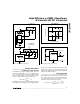
GND
V+
FB
15
6
16
V
IN
V
OUT
R4 = 10kΩ TO 60kΩ
OUT
9
R5
R4
C7*
( )
R5 = R4 -1
V
REF
= 2.0V NOMINAL
* SEE
COMPENSATION CAPACITOR
SECTION.
V
OUT
V
REF
MAX746
EXT
FB
OUT
D1
V
OUT
L
C1
N
12
6
9
R5
26.1k (1%)
C7
R4b
22.6k (1%)
N
R4a
17.4k (1%)
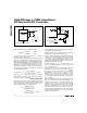
5V/3.3V
V
OUT
= V
REF
+1
( )
R5
R4a
R5
R4a + R4b
( )
MAX746
SELECT WITH FET OFF:
SELECT WITH FET OFF:
V
OUT
= V
REF +1
V
REF
= 2.0V NOMINAL
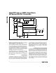
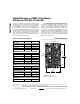
Figure 6. Adjustable Output Circuit
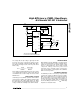
Figure 7. 3.3V/5V Ajustable Output Circuit