
User Manual
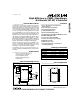

MAX746
High-Efficiency, PWM, Step-Down,
N-Channel DC-DC Controller
_______________________________________________________________________________________ 7
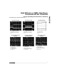
Discontinuous-/Continuous-
Conduction Modes
The MAX746 is designed to operate in continuous-con-
duction mode (CCM) but can also operate in discontinu-
ous-conduction mode (DCM), making it ideal for variable-
load applications. In DCM, the current starts at zero and
returns to zero on each cycle. In CCM, the inductor current
never returns to zero; it consists of a small AC component
superimposed on a DC offset. This results in higher current
capability because the AC component in the inductor cur-
rent waveform is small. It also results in lower output noise,
since the inductor does not exhibit the ringing that would
occur if the current reached zero (see inductor waveforms
in the
Typical Operating Characteristics
). To transfer equal
amounts of energy to the load in one cycle, the peak cur-
rent level for the discontinuous waveform must be much
larger than the peak current for the continuous waveform.
Slope Compensation
Slope compensation stabilizes the inner current-feedback
loop by adding a ramp signal to the current-sense amplifier
output. Ideal slope compensation can be achieved by
adding a linear ramp, with the same slope as the declining
inductor current, to the rising inductor current-sense voltage.
Under these conditions, the inductor must be scaled to the
current-sense resistor value.
Overcompensation adds a pole to the outer voltage feed-
back-loop response, degrading loop stability. This may cause
voltage-mode pulse-frequency-modulation instead of PWM
operation. Undercompensation results in inner current feed-
back-loop instability, and may cause the inductor current to
staircase. Ideal matching between the sense resistor and
inductor is not required; it can differ by ±30% or more.
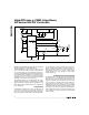
Oscillator and EXT Control
The oscillator frequency is nominally 100kHz, and the duty
cycle varies from 5% to 96%, depending on the input/out-
put voltage ratio. EXT, which provides the gate drive for the
external logic-level N-FET, is switched between HIGH and
GND at the switching frequency. EXT is controlled by a
unique two-comparator control scheme consisting of a PWM
comparator and an idle-mode comparator (Figure 2). The
PWM comparator determines the cycle-by-cycle peak cur-
rent with heavy loads, and the idle-mode comparator sets
the light-load peak current. As V
OUT
begins to drop, EXT
goes high and remains high until both comparators trip.
With heavy loads, the idle-mode comparator trips first and
the PWM control comparator determines the EXT on-time;
2
3
4
6
5
11
LBI
SS
REF
FB
SHDN
AGND
V+
CP
HIGH
AV+
CS
EXT
CC
OUT
LB0
V
IN
6V TO 15V
GND
C6
1.0µF
D2
1N914
*
C8
0.1µF
D4
1N5817
D3
1N914
*
D1
NSQ03A03
5V
AT 3A
L1
39µH
C1
430µF
N
C9
4.7µF
14
13
8
10
12
7
9
1
R2
R1
R
SENSE
40mΩ
R3
100k
C7
2.7nF
C4
0.1µF
C2
100µF
C3
0.1µF
C5
0.1µF
Q1
Si9410DY
15
16
*
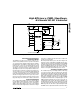
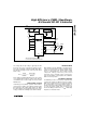
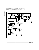
SEE TABLE 2 FOR DIODE SELECTION.
MAX746
Figure 1a. 5V Standard Application Circuit (15W)