
User Manual

MAX746
High-Efficiency, PWM, Step-Down,
N-Channel DC-DC Controller
8 _______________________________________________________________________________________
2
3
4
5
11
LBI
SS
REF
SHDN
AGND
V+
CP
HIGH
AV+
CS
EXT
CC
OUT
FB
LB0
GND
C6
1µF
D2
1N914
C8
0.1µF
14
13
8
10
12
7
9
6
1
R2
R1
C7
2nF
C2
100µF
C3
0.1µF
C5
0.1µF
D3
1N914
C9
1µF
C10
0.1µF
D5
1N914
D4
1N5817
C11
1µF
R4
20k (1%)
R5
13k (1%)
D1
NSQ03A03
L1
*
22µH
C4
0.1µF
N
R
SENSE
40mΩ
R3
100k
Q1
Si9410DY
D6
1N914
3.3V
AT 3A
C3
660µF
15
16
*
SUMIDA CDR125 22µH SURFACE-MOUNT INDUCTOR
MAX746
V
IN
4.5V TO 6V
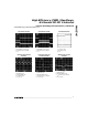
with light loads, the PWM comparator trips quickly and the
idle-mode comparator sets the EXT on-time.
Traditional PWM converters continue to switch on every
cycle, even when the inductor current is discontinuous
due to smaller loads, decreasing light-load efficiency.
In contrast, the MAX746’s idle-mode comparator increas-
es the switch on-time, allowing more energy to be trans-
ferred per cycle. Since fewer cycles are required, the
switching frequency is reduced, resulting in minimal
switching losses and increased efficiency.
The light-load output noise spectrum widens due to the
variable switching frequency in idle-mode, but output
ripple remains low. Using the Typical Operating Circuit,
with a 9V input and a 125mA load current, output ripple
is less than 40mV.
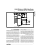
Charge Pump
The MAX746 contains all the control circuitry required
to provide a regulated charge-pump voltage 5V
above V+ for high-side driving N-channel logic FETs.
The charge pump operates with a nominal 50kHz fre-
quency. When the voltage at HIGH exceeds AV+ by
5V, the charge-pump oscillator is inhibited (Figure 2).
When the voltage at HIGH is less than 4.3V below V+,
undervoltage lockout occurs. Use the voltage tripler
(Figure 3b) when V+ ≤ 6V; otherwise, use the voltage
doubler (Figure 3a).
Soft-Start and Current Limiting
The MAX746 draws its highest current at power-up. If
the power source to the MAX746 cannot provide this
initial elevated current, the circuit may not function cor-
rectly. For example, after prolonged use the increased
series resistance of a battery may prevent it from pro-
viding adequate initial surge currents when the
MAX746 is brought out of shutdown. Using soft-start
(SS) minimizes the possibility of overloading the incom-
ing supply at power-up by gradually increasing the
peak current limit. Connect an external capacitor from
SS to AGND to reduce the initial peak currents drawn
from the supply.
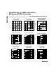
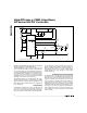
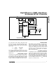
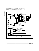
Figure 1b. 3.3V Standard Application Circuit (9.9W)