
User Manual

MAX746
High-Efficiency, PWM, Step-Down,
N-Channel DC-DC Controller
_______________________________________________________________________________________ 9
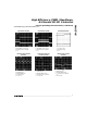
The steady-state SS pin voltage is typically 3.8V. On
power-up, SS sources 1µA until its voltage reaches
3.8V. The current-limit comparator inhibits EXT switch-
ing until the SS voltage reaches 1.8V. The peak current
limit is set by:
V
LIMIT
150mV (typ)
I
PK
=
_________
=
___________
R
SENSE
R
SENSE
where V
LIMIT
is the differential voltage across the current-
sense amplifier inputs. Figure 4 shows how the SS peak
current limit increases as the voltage on SS rises for two
R
SENSE
values.
Undervoltage Lockout
Undervoltage lockout inhibits operation of EXT until the
charge pump is capable of generating a voltage greater
than 4.3V above the supply voltage (Figure 2). When
the undervoltage-lockout comparator detects an under-
voltage condition, the switching action at EXT is halted.
Shutdown Mode
When SHDN is high, the MAX746 is shut down. In this
mode, the internal biasing circuitry (including EXT) is
turned off, V
OUT
drops to 0V, and the supply current
drops to 1.4µA (20µA max). This excludes external
component leakage, which may add several
microamps to the shutdown supply current for the
entire circuit. SHDN is a logic input. Connect SHDN to
GND for normal operation.
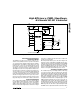
Low-Battery Detector
The MAX746 provides a low-battery comparator that
compares the voltage on LBI to the reference voltage.
LBO, an open-drain output, goes low when the LBI volt-
age is below V
REF
. Use a resistor-divider network, as
shown in the Input Voltage Monitor Circuit (Figure 5),
to set the trip voltage (V
TRIP
) at the desired level. In
this circuit, LBO goes low when V+ ≤ V
TRIP
. LBO is high
impedance in shutdown mode.
2
3
4
6
5
11
LBI
SS
REF
FB
SHDN
AGND
V+
CP
HIGH
AV+
CS
EXT
CC
OUT
LB0
V
IN
6V TO 15V
GND
C6
1µF
D2
1N914
*
C8
0.1µF
D4
1N5817
D3
1N914
*
D1
NSQ03A03
5V
AT 1.5A
L1
**
82µH
C1
220µF
N
C9
4.7µF
14
13
8
10
12
7
9
1
R2
R1
R
SENSE
75mΩ
R3
100k
C7
1nF
C4
0.1µF
C2
47µF
C3
0.1µF
C5
0.1µF
Q1
Si9410DY
15
16
*
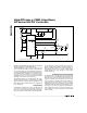
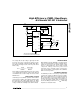
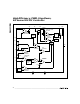
SEE TABLE 2 FOR DIODE SELECTION.
**
SUMIDA CDR125 SURFACE-MOUNT INDUCTOR.
MAX746
Figure 1c. 5V Standard Application Circuit (7.5W)