
User Manual
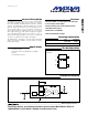

MAX7461
Loss-of-Sync Alarm
2 _______________________________________________________________________________________
ABSOLUTE MAXIMUM RATINGS
Stresses beyond those listed under “Absolute Maximum Ratings” may cause permanent damage to the device. These are stress ratings only, and functional
operation of the device at these or any other conditions beyond those indicated in the operational sections of the specifications is not implied. Exposure to
absolute maximum rating conditions for extended periods may affect device reliability.
V
CC
to GND..............................................................-0.3V to +6V
LOS to GND..............................................................-0.3V to +6V
IN to GND.................-0.3V to the lower of +6V and (V
CC
+ 0.3V)
Continuous Power Dissipation (T
A
= +70°C)
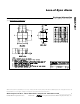
5-Pin SOT23-5 (derate 7.1mW/°C above +70°C) ......571.0mW
Maximum Current Into Any Pin .........................................±50mA
Operating Temperature Range
MAX7461EUK ...................................................-40°C to +85°C
Storage Temperature Range .............................-65°C to +150°C
Lead Temperature (soldering, 10s) .................................+300°C
Junction Temperature......................................................+150°C
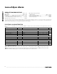
ELECTRICAL CHARACTERISTICS
(V
CC
= +4.5V to +5.5V, GND = 0, C
IN
= 0.1µF, RO = 500Ω, T
A
= -40°C to +85°C, unless otherwise noted. Typical values are at T
A
=
+25°C.)
PARAMETER
SYMBOL
CONDITIONS
MIN
TYP
MAX
UNITS
AC CHARACTERISTICS
Minimum Input Sync Height
V
IN-MIN
AC-coupled (Note 1) 105 130
mV
P-P
Maximum Input Voltage
V
IN-MAX
AC-coupled 2.4
V
P-P
LOS Release Time t
RT
(Note 2) 1.7 2.2 2.7
LOS Detect Time t
DT
(Note 3) 1.9 3.4 4.9
ms
DIGITAL CHARACTERISTICS
Output Low Voltage V
OL
I
SINK
= 10mA 0.4 V
Logic High Leakage Current I
OLEAK
1µA
POWER REQUIREMENTS
Supply Voltage V
CC
4.5 5.0 5.5 V
Supply Current I
CC
1.7 2.2 mA
Power-Supply Noise Immunity V
PSNI
0 to 5MHz sinusoid on V
CC
(Note 4) 200
mV
P-P
Note 1: Minimum input sync height is the voltage above which LOS is guaranteed to be in high-impedance mode after the maximum
LOS time-constant time.
Note 2: LOS release time is the time that the video input must be continuously present before LOS goes high (inactive state).
Note 3: The LOS detect time is the time that the video input must be continuously absent before LOS goes low (active state).
Note 4: The MAX7461 LOS output is accurate with a power-supply noise level below V
PSNI
.