
User guide


Slow UVP
If the output drops below 80% of the nominal output
voltage (V
REFIN
) for 75µs, the MAX8737 shuts down the
LDO and pulls the DRV_ pin to ground. If the output
voltage returns above 80% of the nominal output volt-
age (V
REFIN
) within the 75µs, the controller ignores the
load transient.
Fast UVP
If the output voltage drops below 60% of the nominal
output voltage (V
REFIN
) for approximately 5µs, the
MAX8737 immediately shuts down and pulls the DRV_
pin to ground. If the output voltage returns above 80%
of the nominal output voltage (V
REFIN
) within the 5µs,
the controller ignores the load transient.
Thermal Protection
The MAX8737 is available in a thin QFN package to
reduce the thermal impedance, and improve the ther-
mal coupling between the controller and the external
MOSFETs. When the controller’s junction temperature
exceeds T
J
= +125°C (max), a thermal sensor turns off
the external pass transistor, allowing the system to
cool. The thermal sensor turns the pass transistor back
on once the controller’s junction temperature drops by
approximately 20°C.
Design Procedure
Input Capacitor Selection (C
IN
)
Typically, the MAX8737 is powered from the output of a
step-down regulator, effectively providing a low-imped-
ance source. A local 10µF ceramic capacitor at V
IN
and
a 1.0µF ceramic capacitor at V
BIAS
should be sufficient
for most applications. If the linear regulator is connect-
ed to a high-impedance input, low-ESR polymer capac-
itors are recommended on the input.
Output Capacitor Selection (C
OUT
)
To maintain stability and provide good transient
response, the MAX8737 requires 4.7µF/A (4.7µF mini-
mum) of low ESR ceramic capacitor at the output. The
regulator remains stable with capacitances higher than
the minimum. When selecting the output capacitor to
MAX8737
Dual, Low-Voltage Linear Regulator Controllers
with External MOSFETs
______________________________________________________________________________________ 11
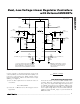
V
OUT
C
OUT
R
CS
C
IN
INPUT
R3
C2
CS
OUT
DRV
MAX8737
MAX8737
V
OUT
C
OUT
R
CS
C
IN
INPUT
R3
C2
CS
OUT
DRV
R1
R2
10mV
R
CS
I
MAX
V
OUT
10mV
R
CS
I
MAX
V
OUT
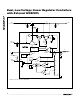
SIMPLE CURRENT-LIMIT PROTECTION
FOLDBACK CURRENT-LIMIT PROTECTION
Figure 3. Current-Limit Protection