
User guide

MAX8737
Dual, Low-Voltage Linear Regulator Controllers
with External MOSFETs
_______________________________________________________________________________________ 7
MAX8737
Dual, Low-Voltage Linear Regulator Controllers
with External MOSFETs
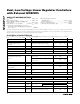
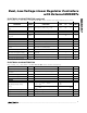
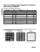
Pin Description
PIN NAME FUNCTION
1V
CC
Analog and Driver Supply Input. Connect to the system supply voltage (+5.0V). Bypass V
CC
to analog
ground with a 1µF or greater ceramic capacitor.
2 CS1
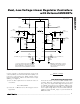
Positive Current-Sense Input for LDO1. To enable (foldback) current limit, connect CS1 to the positive
terminal of the current-sense element as shown in Figure 1. The MAX8737 driver reduces the gate
voltage when the 10mV (typ) current-limit threshold is exceeded. When CS1 is connected to V
CC
, the
MAX8737 disables the current-limit protection and enables the output undervoltage protection (see the
UVP Short-Circuit Protection section).
3 OUT1
Outp ut Feed b ack- S ense, N eg ati ve C ur r ent- S ense, and D i schar g e Inp ut for LD O 1. C onnect d i r ectl y to the
l i near r eg ul ator outp ut. W hen LD O1 i s d i sab l ed , OU T1 i s d i schar g ed thr oug h an i nter nal 10Ω FE T to GN D .
4 REFIN1 External Reference Input for LDO1. REFIN1 sets the main output regulation voltage (V
OUT1
= V
REFIN1
).
5
PGOOD2
Open-Drain Power-Good Output for LDO2. PGOOD2 is low when the output voltage is more than 12%
(typ) below the normal regulation point, during soft-start, and in shutdown. Approximately 2ms (typ) after
OUT2 reaches the regulation voltage (REFIN2), PGOOD2 becomes high impedance as long as the
output remains in regulation.
6
PGOOD1
Open-Drain Power-Good Output for LDO1. PGOOD1 is low when the output voltage is more than 12%
(typ) below the normal regulation point, during soft-start, and in shutdown. Approximately 2ms (typ) after
OUT1 reaches the regulation voltage (REFIN1), PGOOD1 becomes high impedance as long as the
output remains in regulation.
7 EN2
Enable Input for LDO2. Connect EN2 to Vcc for always ON. When EN2 is pulled low, the linear regulator
shuts down and pulls the output to ground.
8 EN1
Enable Input for LDO1. Connect EN1 to Vcc for always ON. When EN1 is pulled low, the linear regulator
shuts down and pulls the output to ground.
9 REFIN2
External Reference Input for the Secondary Regulator (LDO2). REFIN2 sets the main output regulation
voltage (V
OUT2
= V
REFIN2
).
10 OUT2
Output Sense, Negative Current-Sense Input, and Discharge Input for the Secondary Regulator (LDO2).
Connect directly to the linear regulator output. When the LDO2 is disabled, OUT2 is discharged through
an internal 10Ω FET to GND.
11 CS2
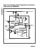
Positive Current-Sense Input for LDO2. To enable (foldback) current limit, connect CS2 to the positive
terminal of the current-sense element as shown in Figure 1. The MAX8737 driver reduces the gate
voltage when the 10mV (typ) current-limit threshold is exceeded. When CS2 is connected to V
CC
, the
MAX8737 disables the current-limit protection and enables the output undervoltage protection (see the
UVP Short-Circuit Protection section).
12, 14 N.C. Not Internally Connected
13 DRV2 External N-Channel Gate Drive for LDO2
15 GND Ground. Connect the thin QFN backside pad to GND.
16 DRV1 External N-Channel Gate Drive for LDO1
—EPExposed Pad. Connect the thin QFN backside pad to GND.