
User guide

resistor network is calculated using the short-circuit
current (I
SHORT
), the maximum load current (I
MAX
), cur-
rent-sense resistor (R
CS
), the 10mV (±3mV) current-
limit threshold (V
ILIM
), and the external reference input
(REFIN_). See Figure 3:
1) Pick the R
CS
requirement for maximum short-cir-
cuit current:
2) Select R1 = 10Ω and select R2 using the follow-
ing formula:
UVP Short-Circuit Protection
There are two levels of short-circuit UVP available in the
controller. When the current-limit protection is not used
(CS_= V
CC
), the output undervoltage timeout protection
is enabled, which protects the regulator against short
circuits. Output UVP timing depends on the magnitude
of the output voltage drop. To clear the UVP fault latch,
toggle the respective EN_ input, or cycle V
CC
below its
UVLO threshold.
R
VVR
IR V
REFIN ILIM
MAX CS ILIM
2
1
=
+
−
()
RVI
CS ILIM SHORT
= /
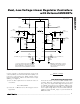
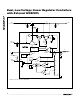
MAX8737
Dual, Low-Voltage Linear Regulator Controllers
with External MOSFETs
_______________________________________________________________________________________ 9
R6B
100kΩ
POWER
GOOD 2
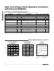
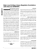
* A LOCAL 10µF CERAMIC CAPACITOR WILL BE SUFFICIENT
FOR MOST APPLICATIONS. IF THE MAX8737 IS POWERED
FROM A HIGH-IMPEDANCE SOURCE, ADDITIONAL LOW-ESR
POLYMER CAPACITORS ARE RECOMMENDED ON THE INPUT.
N2
R3B
33Ω
C2B
0.22µF
C
IN2
10µF
C
SYS2
*
100µF
C
OUT2
22µF
1.05V
3A (MAX)
INPUT
1.25V TO 1.5V
ON
OFF
R2A
100kΩ
R1A
33.2kΩ
ON
OFF
R6A
100kΩ
POWER
GOOD 1
C
IN1
10µF
C
SYS1
*
100µF
C
OUT1
10µF
1.5V
2A (MAX)
C1
1.0µF
5V BIAS
SUPPLY
INPUT
1.8V TO 2.5V
R3A
27Ω
C2A
0.1µF
GND
REFIN1
EN1
OUT1
DRV1
PGOOD1
V
CC
PGOOD2
DRV2
OUT2
EN2
MAX8737
NOTE: THE SYSTEM REFERENCE IS TYPICALLY
GENERATED BY THE STEP-DOWN CONVERTER
USED TO POWER THE DUAL LOW-VOLTAGE
LINEAR REGULATORS.
R4B
10Ω
R5B
150Ω
R1B
90kΩ
R2B
100kΩ
SYSTEM REF (2.0V)
SYSTEM REF (2.0V)
R4A
10Ω
R5A
340Ω
N1
REFIN2
R
CS2
20mΩ
R
CS1
20mΩ
CS1
CS2
N1/N2: Si 4922DY
Figure 1. Typical Operating Circuit with Current Limit