
User guide

MAX9039–MAX9043/MAX9050–MAX9053
3) In this example, let V
CC
= 5V and V
REF
= 2.5V:
and
4) Select R2. In this example, we will choose 1kΩ.
5) Select V
HYS
. In this example, we will choose 50mV.
6) Solve for R1:
where R1 ≈ 100kΩ, V
TH
= 2.525V, and V
TL
= 2.475V.
Board Layout and Bypassing
Power-supply bypass capacitors are not typically need-
ed, but would be called for in cases where supply
impedance is high, supply leads are long, or excessive
noise is expected on the supply lines. Use 100nF
bypass capacitors under these conditions. Minimize
signal trace lengths to reduce stray capacitance.
Reference Output/Load Capacitance
The MAX9039/MAX904_/MAX905_ do not require an
output capacitor on REF for frequency stability. They
are stable for capacitive loads up to 4.7nF. However, in
applications where the load or the supply can experi-
ence step changes, an output capacitor will reduce the
amount of overshoot (or undershoot) and assist the cir-
cuit’s transient response. When an application is not
subject to transient conditions, the REF capacitor can
be omitted.
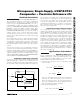
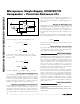
Biasing for Data Recovery
Digital data is often embedded into a bandwidth- and
amplitude-limited analog path. Recovering the data can
be difficult. Figure 2 compares the input signal to a
time-averaged version of itself. This self-biases the
threshold to the average input voltage for optimal noise
margin.
Even severe phase distortion is eliminated from the dig-
ital output signal. Be sure to choose R1 and C1 so that:
where f
CAR
is the fundamental carrier frequency of the
digital data stream.
UCSP Package Consideration
For general UCSP package information and PC layout
considerations, please refer to Maxim Application
Note,"Wafer-Level Chip-Scale Package."
UCSP Reliability
The chip-scale package (UCSP) represents a unique
packaging form factor that may not perform equally to a
packaged product through traditional mechanical relia-
bility tests. UCSP reliability is integrally linked to the
user’s assembly methods, circuit board material, and
usage environment. The user should closely review
these areas when considering use of a UCSP.
Performance through Operating Life Test and Moisture
Resistance remains uncompromised as it is primarily
determined by the wafer-fabrication process.
Mechanical stress performance is a greater considera-
tion for a UCSP. UCSPs are attached through direct
solder contact to the user’s PC board, foregoing the
inherent stress relief of a packaged product lead frame.
Solder joint contact integrity must be considered.
Information on Maxim’s qualification plan, test data,
and recommendations are detailed in the UCSP appli-
cation note, which can be found on Maxim’s website at
www.maxim-ic.com.
Chip Information
MAX9039 TRANSISTOR COUNT: 193
MAX9040/MAX9041/MAX9050/MAX9051 TRANSISTOR
COUNT: 204
MAX9042/MAX9043/MAX9052/MAX9053 TRANSISTOR
COUNT: 280
f
1
2R1C1
CAR
>>
π
0 050 5
1000
1 1000
. =
+
R
VV
R
RR
HYS CC
=
+
2
12
V
R
RR
TL
=−
+
25 1
2
12
.
V
R
RR
TH
=+
+
25 25
2
12
..
Micropower, Single-Supply, UCSP/SOT23
Comparator + Precision Reference ICs
10 ______________________________________________________________________________________
MAX9039–MAX9043
MAX9050–MAX9053
OUT
IN+
IN-
10kΩ
0.1µF
V
CC
V
IN
V
EE
V
CC
Figure 2. Time Averaging of the Input Signal for Data Recovery