
User Manual

��������������������������������������������������������������� Maxim Integrated Products 120
MAX98089
Low-Power, Stereo Audio Codec
with FlexSound Technology
The slave address with the R/W bit set to 0 indicates
that the master intends to write data to the ICs. The ICs
acknowledge receipt of the address byte during the
master-generated 9th SCL pulse.
The second byte transmitted from the master configures
the IC’s internal register address pointer. The pointer tells
the IC where to write the next byte of data. An acknowl-
edge pulse is sent by the ICs upon receipt of the address
pointer data.
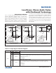
The third byte sent to the ICs contains the data that is writ-
ten to the chosen register. An acknowledge pulse from the
ICs signals receipt of the data byte. The address pointer
autoincrements to the next register address after each
received data byte. This autoincrement feature allows a
master to write to sequential registers within one continu-
ous frame. The master signals the end of transmission by
issuing a STOP condition. Register addresses greater
than 0xC7 are reserved. Do not write to these addresses.
Read Data Format
Send the slave address with the R/W bit set to 1 to initi-
ate a read operation. The IC acknowledges receipt of
its slave address by pulling SDA low during the 9th SCL
clock pulse. A START command followed by a read com-
mand resets the address pointer to register 0x00.
The first byte transmitted from the ICs is the content of
register 0x00. Transmitted data is valid on the rising
edge of SCL. The address pointer autoincrements after
each read data byte. This autoincrement feature allows
all registers to be read sequentially within one continuous
frame. A STOP condition can be issued after any number
of read data bytes. If a STOP condition is issued followed
by another read operation, the first data byte to be read
is from register 0x00.
The address pointer can be preset to a specific register
before a read command is issued. The master presets the
address pointer by first sending the IC’s slave address
with the R/W bit set to 0 followed by the register address.
A REPEATED START condition is then sent followed by the
slave address with the R/W bit set to 1. The IC then trans-
mits the contents of the specified register. The address
pointer autoincrements after transmitting the first byte.
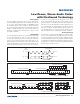
The master acknowledges receipt of each read byte
during the acknowledge clock pulse. The master must
acknowledge all correctly received bytes except the last
byte. The final byte must be followed by a not acknowl-
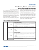
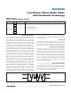
edge from the master and then a STOP condition. Figure
38 illustrates the frame format for reading one byte from
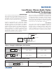
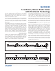
the IC. Figure 39 illustrates the frame format for reading
multiple bytes from the ICs.
Figure 38. Reading One Byte of Data from the ICs
Figure 39. Reading n Bytes of Data from the ICs
ACKNOWLEDGE FROM MAX98089 ACKNOWLEDGE FROM MAX98089 ACKNOWLEDGE FROM MAX98089
NOT ACKNOWLEDGE FROM MASTER
AUTOINCREMENT INTERNAL REGISTER ADDRESS POINTER
1 BYTE
P
REPEATED START
S
O A
A
Sr
1
A
A
SLAVE ADDRESS REGISTER ADDRESS
SLAVE ADDRESS
DATA BYTE
R/W
R/W
ACKNOWLEDGE FROM MAX98089 ACKNOWLEDGE FROM MAX98089 ACKNOWLEDGE FROM MAX98089
AUTOINCREMENT INTERNAL REGISTER ADDRESS POINTER
1 BYTE
REPEATED START
S
O
AA
Sr 1
A
A
SLAVE ADDRESS REGISTER ADDRESS SLAVE ADDRESS
DATA BYTE
R/W
R/W