
Owner manual


MAXQ1004
1-Wire and SPI Authentication Microcontroller
15
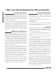
In-Circuit Debug
Embedded debugging capability is available through
the JTAG-compatible test access port (TAP). Embedded
debug hardware and embedded ROM firmware provide
in-circuit debugging capability to the user application,
eliminating the need for an expensive in-circuit emulator.
See Figure 2. The in-circuit debug features include the
following:
• Hardware debug engine
• Set of debug service routines stored in the utility ROM
The embedded hardware debug engine is an indepen-
dent hardware block in the microcontroller. The debug
engine can monitor internal activities and interact with
selected internal registers while the CPU is executing
user code. Collectively, the hardware and software fea-
tures allow two basic modes of in-circuit debugging:
• Background mode allows the host to configure and set
up the in-circuit debugger while the CPU continues to
execute the application software at full speed. Debug
mode can be invoked from background mode.
• Debug mode allows the debug engine to take control
of the CPU, providing read/write access to internal
registers and memory and single-step trace operation.
Applications Information
Grounds and Bypassing
Careful PCB layout significantly minimizes crosstalk
among the high-speed external address/data bus sig-
nals and with digital I/O that could cause improper
operation. The use of multilayer boards is essential to
allow the use of dedicated power planes. Bypass V
DD
on each microcontroller with a 0.1FF capacitor located
as close as possible to the pin.
Design Guidelines for ESD Protection
CMOS design guidelines for any semiconductor require
that no pin be taken above V
DD
or below ground.
Violation of this guideline can result in a hard failure
(damage to the silicon inside the device) or a soft failure
(unintentional modification of memory contents). Voltage
spikes above or below the device’s absolute maximum
ratings can cause a temporary brownout of the internal
power rail, possibly corrupting memory.
Microcontrollers commonly experience negative volt-
age spikes through either their power pins or general-
purpose I/O pins. Negative voltage spikes on power pins
are especially problematic as they directly couple to the
internal power buses. Devices such as keypads can
conduct electrostatic discharges directly into the micro-
controller and seriously damage the device. System
designers must protect components against these tran-
sients that can corrupt system memory.
In a practical application, it is difficult to remove all volt-
ages above V
DD
or below ground. Undershoots of 0.3V
can be tolerated by the microcontroller, and 5V tolerant
pins can accept up to 5.5V. Figure 3 demonstrates a
diode protection scheme that can be used to protect the
I/O pins of a microcontroller. The scheme relies on the
use of a Schottky diode and current limiting resistor to
reduce the effect of current spikes on the device. When
the voltage approaching the device pin exceeds V
DD
or GND by more than 0.1V to 0.2V, the Schottky diodes
become forward biased, conducting the excess voltage
away from the device pins. The current limiting resistors
also help dampen the effect of the voltage spike on the
microcontroller.
Figure 2. In-Circuit Debugger
TAP
CONTROLLER
CPU
DEBUG
ENGINE
DEBUG
SERVICE
ROUTINES
(UTILITY ROM)
CONTROL
BREAKPOINT
ADDRESS
DATA
MAXQ1004
TMS
TCK
TDI
TDO