
Owner manual


MAXQ1004
1-Wire and SPI Authentication Microcontroller
5
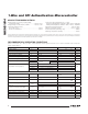
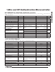
RECOMMENDED DC OPERATING CONDITIONS (continued)
(V
DD
= 1.7V to 3.6V, T
A
= -40NC to +85NC, unless otherwise noted. Typical values are at T
A
= +25NC and V
DD
= 3.3V, unless oth-
erwise noted.) (Note 1)
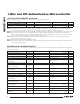
10-BIT ADC PERFORMANCE
(V
DD
= 1.7V to 3.6V, V
REF
= 1.845V, T
A
= -40NC to +85NC, unless otherwise noted.)
PARAMETER SYMBOL CONDITIONS MIN TYP MAX UNITS
INTERNAL OSCILLATOR
Oscillator Frequency f
OSC
5 6 7 MHz
Oscillator Startup Time t
OSC_RDY
V
REG18
= 1.8V (Note 6) 350
Fs
Oscillator Duty Cycle (Note 6) 45 55 %
NANOPOWER RING OSCILLATOR
Nanopower Ring Frequency f
NANO
T
A
= +25NC
3 11 22 kHz
Nanopower Ring Current I
NANO
Typical at V
DD
= 3.0V, active
during wake-up (Note 6)
120 400 nA
Wakeup Timer Interval t
WAKEUP
1/f
NANO
t
NANO
65,535
x t
NANO
s
FLASH MEMORY
Flash Erase Time
Mass erase 20 40
ms
Page erase 20 40
Flash Programming Time per Word t
PROG
20 40
Fs
Write/Erase Cycles 1000 Cycles
Data Retention
T
A
= +25NC
100 Years
Analog Supply Voltage V
AVDD
V
DD
V
PARAMETER SYMBOL CONDITIONS MIN TYP MAX UNITS
Resolution 10 Bits
ADC Clock Frequency f
ACLK
f
SYSCLK
MHz
ADC Clock Period t
ACLK
1/f
ACLK
Fs
AN0 Input Voltage Range V
AN0
V
GND
V
AVDD
V
Analog Input Capacitance C
AIN
1 pF
Integral Nonlinearity INL (Note 6)
Q2
LSB
Differential Nonlinearity DNL No missing codes over temperature
Q1
LSB
Offset Error V
OS
Q2
LSB
ADC Active Current Consumption I
ADC
ACLK = 6MHz, internal reference
on, ADEN = 1 (Note 6)
100 150
FA
ADC Setup Time t
ADC_SETUP
25
Fs
ADC Output Latency t
ADC
1025 t
ACLK
ADC Settling Time t
ADC_SETTLE
Settling time due to channel, refer-
ence or scale change (not produc-
tion tested)
10
Fs
ADC Throughput f
ADC
f
ADC
/t
ADC
ksps
TEMPERATURE SENSOR
Temperature Sensor Setup Time t
TSN_SETUP
25
Fs
Temperature Sensor Error
D
TSN
Q6 NC