
Owner manual


MAXQ1004
1-Wire and SPI Authentication Microcontroller
8
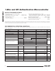
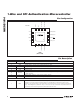
Pin Configuration
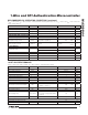
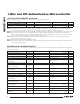
Pin Description
15
16
14
13
6
5
7
DQ
P0.1/INT1/MISO
8
RST
AN0
P0.6/INT6/TMS
AVREF
1 2
GND
4
12 11 9
REG18
V
DD
+
P0.5/INT5/TDI/T0G
P0.4/INT4/TCK/T0
P0.3/INT3/SSEL
P0.2/INT2/SCLK
EP
P0.0/INT0/MOSI P0.7/INT7/TDO
3
10
AVDD
TQFN
(4mm × 4mm)
TOP VIEW
MAXQ1004
PIN NAME FUNCTION
POWER PINS
11 AN0 Analog Input 0. This pin is the analog input to the ADC.
12 AVREF Analog Voltage Reference. Do not connect anything external to this pin.
13 AVDD Analog Supply Voltage. Directly connect AVDD to DVDD.
14 GND Digital Ground
15 REG18
Regulator Capacitor. This pin must be connected to ground through an external 1FF low ESR
(< 5I) capacitor.
16 V
DD
Digital Supply Voltage. +3.3V nominal supply voltage.
— EP Exposed Pad. Connect the EP to the ground plane.
RESET AND STATUS PINS
1
RST
Active-Low Reset. This bidirectional pin recognizes external active-low reset inputs and
employs an internal pullup resistor to allow for a combination of wired-OR external reset
sources. This pin also acts as an output when the source of the reset is internal to the device
(e.g., watchdog timer, power-fail, etc.). In this case, the pin is low while the processor is in a
reset state, and it returns high as the processor exits this state.