NUC130 Series DATA SHEET Cortex™-M0 32-BIT MICROCONTROLLER NuMicro Cortex™-M0 NUC130 Product Data Sheet The information described in this document is the exclusive intellectual property of Nuvoton Technology Corporation and shall not be reproduced without permission from Nuvoton. Nuvoton is providing this document only for reference purposes of NuMicro microcontroller based system design. Nuvoton assumes no responsibility for errors or omissions.
NUC130 Series DATA SHEET Table of Contents1 2 3 GENERAL DESCRIPTION ......................................................................................................... 5 FEATURES ................................................................................................................................. 6 PARTS INFORMATION LIST AND PIN CONFIGURATION .................................................... 10 3.1 NUC130 Products Selection Guide ........................................................
NUC130 Series DATA SHEET 5.9 Timer Controller ............................................................................................................ 42 5.9.1 5.9.2 5.10 Watchdog Timer............................................................................................................ 43 5.11 UART Interface Controller ............................................................................................ 44 5.11.1 5.11.2 5.12 5.13 Functional Description ............................
NUC130 Series DATA SHEET 7.4.4 7.4.5 7.4.6 7.4.7 8 PACKAGE DIMENSIONS ......................................................................................................... 67 8.1.1 8.1.2 8.1.3 9 Specification of Brownout Detector.................................................................................64 Specification of Power-On Reset (5V) ............................................................................64 Specification of Temperature Sensor ......................................
NUC130 Series DATA SHEET 1 GENERAL DESCRIPTION The NUC130 series are 32-bit microcontrollers with embedded ARM® Cortex™-M0 core for industrial control and applications support CAN bus network. The Cortex™-M0 is the newest ARM embedded processor with 32-bit performance and at a cost equivalent traditional 8-bit microcontroller. The NUC130 series embeds Cortex™-M0 core running up to 50 MHz with 64K/128K-byte embedded flash and 8K/16K-byte embedded SRAM.
NUC130 Series DATA SHEET 2 FEATURES • Core – ARM® Cortex™-M0 core runs up to 50 MHz. – One 24-bit system timer. – Supports low power sleep-mode. – Single-cycle 32-bit hardware multiplier. – NVIC for the 32 interrupt inputs, each with 4-levels of priority. – Serial Wire Debug supports with 2 watchpoints/4 breakpoints. • Wide operating voltage ranges from 2.5V to 5.5V • Flash EPROM Memory – 64K/128K bytes Flash EPROM for program code.
NUC130 Series DATA SHEET • Timers – 4 sets of 24-bit timer with 8-bit prescaler. – Counter auto reload. • Watch Dog Timer – Default ON/OFF by configuration setting – Multiple clock sources – 8 selectable time out period from 6ms ~ 3.0sec (depends on clock source) – WDT can wake up power down/sleep. – Interrupt or reset selectable on watchdog time-out.
NUC130 Series DATA SHEET • I2C – Two sets of I2C device. – Master/Slave up to 1Mbit/s – Bidirectional data transfer between masters and slaves – Multi-master bus (no central master). – Arbitration between simultaneously transmitting masters without corruption of serial data on the bus – Serial clock synchronization allows devices with different bit rates to communicate vian one serial bus. – Serial clock synchronization can be used as a handshake mechanism to suspend and resume serial transfer.
NUC130 Series DATA SHEET • One built-in temperature sensor with 1℃ resolution. • Brown-out detector – With 4 levels: 4.5V/3.8V/2.7V/2.2V – Support Brownout Interrupt and Reset option • One built-in LDO • Low Voltage Reset • Operating Temperature: -40℃~85℃ • Packages: – All Green package (RoHS) LQFP 100-pin / 64-pin / 48-pin -9- Publication Release Date: May 31, 2010 Revision V1.
NUC130 Series DATA SHEET 3 3.1 Part number PARTS INFORMATION LIST AND PIN CONFIGURATION NUC130 Products Selection Guide Connectivity Flash SRAM UART SPI/SSI NUC130LE3AN 128 KB 16 KB 2 I2 S IC LIN CAN PWM Comp.
NUC130 Series DATA SHEET PA.3/ADC3 PA.2/ADC2 PA.1/ADC1 PA.0/ADC0 AVSS VSS2 VDD2 ICE_CK ICE_DAT PA.12/PWM0 PA.13/PWM1 PA.14/PWM2 PA.15/PWM3/I2SMCLK PC.8/SS10 PC.9/SPICLK1 PC.10/MISO10 PC.11/MOSI10 PC.12/MISO11 PC.13/MOSI11 PE.0/PWM6 PE.1/PWM7 PE.2 PE.3 PE.4 73 72 71 70 69 68 67 66 65 64 63 62 61 60 59 58 57 56 55 54 53 52 51 NUC130 LQFP 100 pin PA.4/ADC4 3.2.1 74 Pin Configuration 75 3.2 ADC5/PA.5 76 50 PB.9/SS11/TM1 ADC6/PA.6 77 49 PB.
NUC130 Series DATA SHEET PA.4/ADC4 PA.3/ADC3 PA.2/ADC2 PA.1/ADC1 PA.0/ADC0 AVSS ICE_CK ICE_DAT PA.12/PWM0 PA.13/PWM1 PA.14/PWM2 PA.15/PWM3/I2SMCLK PC.8/SS10 PC.9/SPICLK1 PC.10/MISO10 PC.11/MOSI10 48 47 46 45 44 43 42 41 40 39 38 37 36 35 34 33 NUC130 LQFP 64 pin ADC5/PA.5 49 32 PB.9/TM1 ADC6/PA.6 50 31 PB.10/TM2 ADC7//PA.7 51 30 PB.11/TM3/PWM4 AVDD 52 29 PE.5/PWM5 CPN0/PC.7 53 28 PC.0/SS00/I2SLRCLK CPP0/PC.6 54 27 PC.1/SPICLK0/I2SBCLK CPN1/PC.
NUC130 Series DATA SHEET PA.4/ADC4 PA.3/ADC3 PA.2/ADC2 PA.1/ADC1 PA.0/ADC0 AVSS ICE_CK ICE_DAT PA.12/PWM0 PA.13/PWM1 PA.14/PWM2 PA.15/PWM3/I2SMCLK 36 35 34 33 32 31 30 29 28 27 26 25 NUC130 LQFP 48 pin ADC5/PA.5 37 24 PC.0/SS00/I2SLRCLK ADC6/PA.6 38 23 PC.1/SPICLK0/I2SBCLK ADC7/PA.7 39 22 PC.2/MISO00/I2SDI AVDD 40 21 PC.3/MOSI00/I2SDO CPN0/PC.7 41 20 PD.15/TX2 CPP0/PC.6 42 19 PD.14/RX2 INT1/PB.15 43 18 PD.7/CANTX0 XT1_Out 44 17 PD.
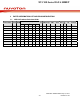
NUC130 Series DATA SHEET 3.3 3.3.1 Pin Description NUC130 Pin Description Pin No. LQFP 100 LQFP 64 LQFP Pin Name Pin Type 48 Description 1 PE.15 I/O General purpose input/output digital pin 2 PE.14 I/O General purpose input/output digital pin 3 PE.13 I/O General purpose input/output digital pin PB.14 I/O General purpose input/output digital pin /INT0 I /INT0: External interrupt1 input pin /SPISS31 I/O /SPISS31: SPI3 2nd slave select pin PB.
NUC130 Series DATA SHEET Pin No. LQFP 100 LQFP 64 LQFP Pin Name Pin Type 48 PD.10 15 MISO30 16 17 19 20 21 10 11 8 9 12 General purpose input/output digital pin I/O MISO30: SPI3 MISO (Master In, Slave Out) pin I PD.11 I/O General purpose input/output digital pin MOSI30 O MOSI30: SPI3 MOSI (Master Out, Slave In) pin PD.12 I/O General purpose input/output digital pin MISO31 18 Description nd MISO31: SPI3 2 I PD.
NUC130 Series DATA SHEET Pin No. LQFP 100 LQFP 64 33 18 34 19 LQFP Pin Name Pin Type 48 14 15 Description PB.1 I/O General purpose input/output digital pin TX0 O TX0: Data transmitter output pin for UART0 PB.2 I/O General purpose input/output digital pin RTS0 35 20 16 PB.3 RTS0: Request to Send output pin for UART0 General purpose input/output digital pin I/O CTS0 36 21 17 PD.
NUC130 Series DATA SHEET Pin No. LQFP 100 LQFP 64 LQFP Pin Name Pin Type 48 Description /SPISS00 I/O /SPISS00: SPI0 slave select pin I2SLRCLK I/O I2SLRCLK: I2S left right channel clock PE.6 I/O General purpose input/output digital pin PE.5 I/O General purpose input/output digital pin PWM5 O PWM5: PWM output PB.11 I/O General purpose input/output digital pin TM3 O TM3: Timer3 external counter input PWM4 O PWM4: PWM output PB.
NUC130 Series DATA SHEET Pin No. LQFP 100 LQFP 64 LQFP Pin Name Pin Type 48 MISO10 60 61 62 63 64 65 Description MISO10: SPI1 MISO (Master In, Slave Out) pin I PC.9 I/O General purpose input/output digital pin SPICLK1 I/O SPICLK1: SPI1 serial clock pin PC.8 I/O General purpose input/output digital pin /SPISS10 I/O /SPISS10: SPI1 slave select pin PA.15 I/O General purpose input/output digital pin PWM3 O PWM3: PWM output pin I2SMCLK O I2SMCLK: I2S master clock output pin PA.
NUC130 Series DATA SHEET Pin No. LQFP 100 75 76 77 78 LQFP 64 48 49 50 51 LQFP Pin Name Pin Type 48 36 37 38 39 79 80 52 40 81 82 83 ADC3 AI ADC3: ADC analog input PA.4 I/O General purpose input/output digital pin ADC4 AI ADC4: ADC analog input PA.5 I/O General purpose input/output digital pin ADC5 AI ADC5: ADC analog input PA.6 I/O General purpose input/output digital pin ADC6 AI ADC6: ADC analog input PA.
NUC130 Series DATA SHEET Pin No. LQFP 100 LQFP 64 89 55 90 91 LQFP Pin Name Pin Type 48 56 57 43 Description PC.15 I/O General purpose input/output digital pin CPN1 I CPN1: Comparator1 Negative input pin PC.14 I/O General purpose input/output digital pin CPP1 I PB.
NUC130 Series DATA SHEET 4 4.1 BLOCK DIAGRAM NUC130 Block Diagram FLASH 128KB ISP 4KB Cortex-M0 50MHz SRAM 16KB PDMA 10 kHz GPIO A,B,C,D,E CLK_CTL P L L 32 KHz 22 MHz 12 MHz LDO 2.5V~ 5.
NUC130 Series DATA SHEET 5 5.1 FUNCTIONAL DESCRIPTION ARM® Cortex™-M0 core The Cortex™-M0 processor is a configurable, multistage, 32-bit RISC processor. It has an AMBA AHB-Lite interface and includes an NVIC component. It also has optional hardware debug functionality. The processor can execute Thumb code and is compatible with other Cortex-M profile processor. Figure 5-1 shows the functional blocks of processor.
NUC130 Series DATA SHEET – Dedicated non-Maskable Interrupt (NMI) input. – Support for both level-sensitive and pulse-sensitive interrupt lines – Wake-up Interrupt Controller (WIC), providing ultra-low power sleep mode support. • Debug support – Four hardware breakpoints. – Two watchpoints. – Program Counter Sampling Register (PCSR) for non-intrusive code profiling. – Single step and vector catch capabilities.
NUC130 Series DATA SHEET 5.2 System Manager 5.2.1 Overview The following functions are included in system manager section y System Memory Map y System Timer (SysTick) y Nested Vectored Interrupt Controller (NVIC) y System management registers for product ID y System management registers for chip and module functional reset and multi-function pin control y Brown-Out and chip miscellaneous Control Register y Combined peripheral interrupt source identify 5.2.
NUC130 Series DATA SHEET 5.2.3 System Timer (SysTick) The Cortex-M0 includes an integrated system timer, SysTick. SysTick provides a simple, 24-bit clear-on-write, decrementing, wrap-on-zero counter with a flexible control mechanism. The counter can be used in several different ways, for example: y y y y y An RTOS tick timer which fires at a programmable rate (for example 100Hz) and invokes a SysTick routine. A high speed alarm timer using Core clock.
NUC130 Series DATA SHEET 5.2.4 Nested Vectored Interrupt Controller (NVIC) Cortex-M0 provides an interrupt controller as an integral part of the exception mode, named as “Nested Vectored Interrupt Controller (NVIC)”.
NUC130 Series DATA SHEET Table 5-1 Exception Model Exception Name Vector Number Priority Reset 1 -3 NMI 2 -2 Hard Fault 3 -1 Reserved 4 ~ 10 Reserved SVCall 11 Configurable Reserved 12 ~ 13 Reserved PendSV 14 Configurable SysTick 15 Configurable Interrupt (IRQ0 ~ IRQ31) 16 ~ 47 Configurable Table 5-2 System Interrupt Map Vector Number Interrupt Number (Bit in Interrupt Registers) Interrupt Name Source IP - - Interrupt description 0 ~ 15 - 16 0 BOD_OUT Brown-Out B
NUC130 Series DATA SHEET 25 9 TMR1_INT TMR1 Timer 1 interrupt 26 10 TMR2_INT TMR2 Timer 2 interrupt 27 11 TMR3_INT TMR3 Timer 3 interrupt 28 12 UART02_INT UART0/2 UART0 and UART2 interrupt 29 13 UART1_INT UART1 UART1 interrupt 30 14 SPI0_INT SPI0 SPI0 interrupt 31 15 SPI1_INT SPI1 SPI1 interrupt 32 16 SPI2_INT SPI2 SPI2 interrupt 33 17 SPI3_INT SPI3 SPI3 interrupt 34 18 I2C0_INT I2C0 I2C0 interrupt 35 19 I2C1_INT I2C1 I2C1 interrupt 36 20 CAN0_INT C
NUC130 Series DATA SHEET - 29 - Publication Release Date: May 31, 2010 Revision V1.
NUC130 Series DATA SHEET 5.3 Clock Controller The clock controller generates the clock sources for the whole chip, including all AMBA interface modules and all peripheral clocks. The clock controller also implements the power control function with the individually clock on or off control, clock source selection and a 4-bit clock divider next to clock source selection. The chip will into power-down mode after set the Power-Down bit and then the CPU Cortex-M0 execute the WFI or the WFE instruction.
NUC130 Series DATA SHEET 5.3.2 System Clock & SysTick Clock The system clock has 5 clock sources which were generated from clock generator block. The clock source switch depends on the register HCLK_S(CLKSEL0[2:0]). The block diagram lists below.
NUC130 Series DATA SHEET 5.3.3 Peripherals Clock The peripherals clock had different clock source switch setting which depends on the different peripheral. Please refer the CLKSEL1 & APBCLK register description. 5.3.4 Power down mode (Deep Sleep Mode) Clock When enter into power down mode, some clock sources and peripherals clock and system clock will be disable. Some clock sources and peripherals clock are still active in power down mode.
NUC130 Series DATA SHEET 5.3.5 Frequency Divider Output This device is equipped a power-of-2 frequency divider which is composed by16 chained divide-by-2 shift registers. One of the 16 shift register outputs selected by a sixteen to one multiplexer is reflected to GPIOB.12. Therefore there are 16 options of power-of-2 divided clocks with the frequency from Fin/21 to Fin/216 where Fin is input clock frequency to the clock divider.
NUC130 Series DATA SHEET 5.4 General Purpose I/O 5.4.1 Overview and Features Up to 80 General Purpose I/O pins can be shared with other function pins; it depends on the chip configuration. These 80 pins are arranged in 5 ports named with GPIOA, GPIOB, GPIOC, GPIOD and GPIOE. Each port equips maximum 16 pins. Each one of the 80 pins is independent and has the corresponding register bits to control the pin mode function and data.
NUC130 Series DATA SHEET 5.4.1.3 Open-Drain Mode Explanation Set GPIOx_PMD (PMDn[1:0]) to 10b the GPIOx port [n] pin is in Open-Drain mode and the I/O pin supports digital output function but only with sink current capability, an additional pull-up resister is needed for driving high state. If the bit value in the corresponding bit [n] of GPIOx_DOUT is “0”, the pin drive a “low” output on the pin.
NUC130 Series DATA SHEET 5.5 I2C Serial Interface Controller (Master/Slave) 5.5.1 Introduction I2C is a two-wire, bi-directional serial bus that provides a simple and efficient method of data exchange between devices. The I2C standard is a true multi-master bus including collision detection and arbitration that prevents data corruption if two or more masters attempt to control the bus simultaneously.
NUC130 Series DATA SHEET 5.5.2 Features The I2C bus uses two wires (SDA and SCL) to transfer information between devices connected to the bus.
NUC130 Series DATA SHEET 5.6 PWM Generator and Capture Timer 5.6.1 Introduction This chip has 4 sets of PWM Generators which can be configured as 8 independent PWM outputs, PWM0~PWM7, or as 4 complementary PWM pairs, (PWM0, PWM1), (PWM2, PWM3), (PWM4, PWM5) and (PWM6, PWM7) with 4 programmable dead-zone generators.
NUC130 Series DATA SHEET 5.6.2 Features 5.6.2.1 PWM function features: y Four PWM Generators, each one supports one 8-bit prescaler, one clock divider, PWM-timer, one dead-zone generator and two PWM outputs. y Up to 8 PWM channels or 4 PWM paired channels. y Up to 16 bits resolution. y PWM Interrupt request synchronous with PWM period. y Single-shot or Continuous mode PWM. y Four Dead-Zone generators 5.6.2.2 Capture Function Features: y Timing control logic shared with PWM Generators.
NUC130 Series DATA SHEET 5.7 Real Time Clock (RTC) 5.7.1 Overview Real Time Clock (RTC) unit provides user the real time and calendar message. The clock source of RTC is from an external 32.768KHz crystal connected at pins X32I and X32O or from an external 32.768KHz oscillator output fed at pin X32I. The RTC unit provides the time message(second, minute, hour) in Time Loading Register (TLR) as well as calendar message(day, month, year) in Calendar Loading Register (CLR).
NUC130 Series DATA SHEET 5.8 Serial Peripheral Interface (SPI) Controller 5.8.1 Overview The Serial Peripheral Interface (SPI) is a synchronous serial data communication protocol which operates in full duplex mode. Devices communicate in master/slave mode with 4-wire bi-direction interface.
NUC130 Series DATA SHEET 5.9 Timer Controller 5.9.1 General Timer Controller The timer module includes four channels, TIMER0~TIMER3 (TIMER0 and TIMER1 are at APB1 and TIMER2 and TIMER3 are at APB2), which allow user to easily implement a counting scheme or timing control for applications. The timer can perform functions like frequency measurement, event counting, interval measurement, clock generation, delay timing, and so on.
NUC130 Series DATA SHEET 5.10 Watchdog Timer The purpose of Watchdog Timer is to perform a system reset after the software running into a problem. This prevents system from hanging for an infinite period of time. Besides, this Watchdog Timer supports the function to wakeup CPU from power-down mode. The watchdog timer includes a 19-bit free running counter with programmable time-out intervals. Setting WTE (WDTCR[7]) enables the watchdog timer and the WDT counter starts counting up.
NUC130 Series DATA SHEET 5.11 UART Interface Controller This MCU provides three channels of Universal Asynchronous Receiver/Transmitters (UART). UART0 supports High Speed UART and UART1~2 perform Normal Speed UARTs, besides, only UART0 and UART1 support flow control function. 5.11.1 Overview The Universal Asynchronous Receiver/Transmitter (UART) performs a serial-to-parallel conversion on data received from the peripheral, and a parallel-to-serial conversion on data transmitted from the CPU.
NUC130 Series DATA SHEET Enable 1 B A - 45 - UART_CLK / (A+2), A must >=3 Publication Release Date: May 31, 2010 Revision V1.
NUC130 Series DATA SHEET 5.11.2 Features of UART controller z The UART control supports three channels, UART0, UART1 and UART2. z UART0/UART1/UART2 supports 64/16/16 bytes entry FIFO for received and transmitted data payloads. z Auto flow control/flow control function (/CTS, /RTS) are supported in UART0 and UART1. z Individual programmable baud-rate generator for each channel. z Fully programmable serial-interface characteristics: 5-, 6-, 7-, or 8-bit character.
NUC130 Series DATA SHEET 5.12 Controller Area Network (CAN Bus) 5.12.1 Introduction The Controller Area Network (CAN) is a serial communications protocol which is multi-master and it efficiently supports distributed real-time control with very high level of security. Its domain of application range from high speed networks to low cost multiplex wiring. In automotive electronics, engine control units, sensors, anti-skid-systems, etc. are connected using CAN with bit-rates up to 1Mbit/s.
NUC130 Series DATA SHEET 5.13 PS2 Device Controller (PS2D) 5.13.1 Overview PS/2 device controller provides basic timing control for PS/2 communication. All communication between the device and the host is managed through the CLK and DATA pins. Unlike PS/2 keyboard or mouse device controller, the received/transmit code needs to be translated as meaningful code by firmware. The device controller generates the CLK signal after receiving a request to send, but host has ultimate control over communication.
NUC130 Series DATA SHEET 5.14 I2S Controller 5.14.1 Overview The I2S controller consists of IIS protocol to interface with external audio CODEC. Two 8 word deep FIFO for read path and write path respectively and is capable of handling 8 ~ 32 bit word sizes. DMA controller handles the data movement between FIFO and memory. 5.14.2 Features y APB interface compatible y I2S can operate as either master or slave y Capable of handling 8, 16, 24, and 32 bit word sizes.
NUC130 Series DATA SHEET 5.15 Analog-to-Digital Converter (ADC) 5.15.1 Functional Description NUC1XX series contain one 12-bit successive approximation analog-to-digital converters (SAR A/D converter) with 8 input channels. The A/D converter supports three operation modes: single, singlecycle scan and continuous scan mode. There are two kinds of scan mode: continuous mode and single cycle mode. The A/D converters can be started by software and external STADC/PB.8 pin.
NUC130 Series DATA SHEET 5.16 Analog Comparator 5.16.1 Functional Description NUC1XX series contains two comparators. The comparators can be used in a number of different configurations. The comparator output is a logical one when positive input greater than negative input, otherwise the output is a zero. Each comparator can be configured to cause an interrupt when the comparator output value changes.
NUC130 Series DATA SHEET 5.17 PDMA Controller 5.17.1 Overview The NUC1XX contains a peripheral direct memory access (PDMA) controller that transfers data to and from memory or transfer data to and from APB devices. The PDMA has nine channels of DMA (Peripheral-to-Memory or Memory-to-Peripheral or Memory-to-Memory). For each PDMA channel (PDMA CH0~CH8), there is one word buffer as transfer buffer between the Peripherals APB devices and Memory. Software can stop the PDMA operation by disable PDMA [PDMACEN].
NUC130 Series DATA SHEET 6 6.1 FLASH MEMORY CONTROLLER (FMC) Overview NUC1XX series equips with 128/64/32K bytes on chip embedded Flash EEPROM for application program memory (APROM) that can be updated through ISP/IAP procedure. In System Programming (ISP) function enables user to update program memory when chip is soldered on PCB. After chip power on Cortex-M0 CPU fetches code from APROM or LDROM decided by boot select (CBS) in Config0.
NUC130 Series DATA SHEET 7 7.1 ELECTRICAL CHARACTERISTICS Absolute Maximum Ratings SYMBOL PARAMETER MIN MAX UNIT VDD−VSS -0.3 +7.0 V VIN VSS-0.3 VDD+0.
NUC130 Series DATA SHEET 7.2 DC Electrical Characteristics (VDD-VSS=3.3V, TA = 25°C, FOSC = 50 MHz unless otherwise specified.) SPECIFICATION PARAMETER SYM. MIN. TYP. MAX. UNI T 5.5 V TEST CONDITIONS Operation voltage VDD 2.5 Power Ground VSS AVSS -0.3 LDO Output Voltage (bypass = 0) VLDO -10% 2.45 +10% V VDD > 2.7V LDO Output Voltage (bypass = 0) VLDO -10% VDD +10% V VDD < 2.
NUC130 Series DATA SHEET Operating Current Normal Run Mode @ 4Mhz Operating Current Idle Mode @ 50Mhz Operating Current Idle Mode @ 12Mhz Operating Current Idle Mode @ 4Mhz IDD9 5.8 mA VDD = 5V@4Mhz, enable all IP and XTAL=4MHz disable PLL, IDD10 4.2 mA VDD = V@4Mhz, disable all IP XTAL=4MHz and disable PLL, IDD11 5.1 mA VDD = 3V@4Mhz, enable all IP and XTAL=4MHz disable PLL, IDD12 3.6 mA VDD = 3V@4Mhz, disable all IP and XTAL=4MHz disable PLL, IIDLE1 35 mA VDD= 5.
NUC130 Series DATA SHEET Standby Current Power-down Mode (Deep Sleep Mode) IPWD1 23 μA VDD = 5.5V, RTC OFF, No load @ Disable BOV function IPWD2 18 μA VDD = 3.3V, RTC OFF, No load @ Disable BOV function IPWD3 28 μA VDD = 5.5V, RTC run , No load @ Disable BOV function IPWD4 22 μA VDD = 3.3V, RTC run , No load @ Disable BOV function Input Current PA, PB, PC, PD, PE IIN1 -60 - +15 μA VDD = 5.5V, VIN = 0V or VIN=VDD Input Current at /RESET [1] IIN2 -55 -45 -30 μA VDD = 5.
NUC130 Series DATA SHEET ISR11 -300 -370 -450 μA VDD = 4.5V, VS = 2.4V ISR12 -50 -70 -90 μA VDD = 2.7V, VS = 2.2V ISR12 -40 -60 -80 μA VDD = 2.5V, VS = 2.0V ISR21 -20 -24 -28 mA VDD = 4.5V, VS = 2.4V ISR22 -4 -6 -8 mA VDD = 2.7V, VS = 2.2V ISR22 -3 -5 -7 mA VDD = 2.5V, VS = 2.0V ISK1 10 16 20 mA VDD = 4.5V, VS = 0.45V ISK1 7 10 13 mA VDD = 2.7V, VS = 0.45V ISK1 6 9 12 mA VDD = 2.5V, VS = 0.45V Brownout voltage with BOV_VL [1:0] =00b VBO2.2 2.1 2.
NUC130 Series DATA SHEET 7.3 AC Electrical Characteristics t CLCL t CLCH t CLCX tCHCL t CHCX Note: Duty cycle is 50%. PARAMETER SYMBOL MIN. TYP. MAX. UNITS Clock High Time tCHCX 20 - - nS Clock Low Time tCLCX 20 - - nS Clock Rise Time tCLCH - - 10 nS Clock Fall Time tCHCL - - 10 nS CONDITION MIN. TYP. MAX. UNIT External crystal 4 12 24 MHz Temperature - -40 - 85 ℃ VDD - 2.5 5 5.5 V 7.3.
NUC130 Series DATA SHEET 7.3.1.1 Typical Crystal Application Circuits CRYSTAL C1 C2 R 4MHz ~ 24 MHz without without without C1 XTAL1 R XTAL2 C2 Figure 7-1 Typical Crystal Application Circuit - 60 - Publication Release Date: May 31, 2010 Revision V1.
NUC130 Series DATA SHEET 7.3.2 External 32kHz XTAL Oscillator PARAMETER CONDITION MIN. TYP. MAX. UNIT External crystal - 32.768 - kHz Temperature - -40 - 85 ℃ VDD - 2.5 - 5.5 V VDD = 5V - 5 - uA CONDITION MIN. TYP. MAX. UNIT Supply voltage - 2.5 - 5.5 V Center Frequency - - 22.1184 Calibrated Internal Oscillator Frequency +25°C; VDD =5V -1 - +1 % -40°C~+85°C; VDD=2.5V~5.
NUC130 Series DATA SHEET 7.4 Analog Characteristics 7.4.1 Specification of 12-bit SARADC PARAMETER SYM. MIN. TYP. MAX. UNIT Resolution - - - 12 Bit Differential nonlinearity error DNL - ±3 - LSB Integral nonlinearity error INL - ±4 - LSB Offset error EO - ±1 10 LSB Gain error (Transfer gain) EG - 1 1.
NUC130 Series DATA SHEET 7.4.2 Specification of LDO & Power management PARAMETER MIN TYP MAX UNIT NOTE Input Voltage 2.7 5 5.5 V VDD input voltage Output Voltage -10% 2.45 +10% V LDO output voltage -10% Input Voltage +10% V Input Voltage < 2.
NUC130 Series DATA SHEET 7.4.3 Specification of Low Voltage Reset PARAMETER CONDITION MIN. TYP. MAX. UNIT Operation voltage - 1.7 - 5.5 V Quiescent current VDD5V=5.5V - - 5 uA Temperature - -40 25 85 ℃ Temperature=25° 1.7 2.0 2.3 V Temperature=-40° - 2.4 - V Temperature=85° - 1.6 - V - 0 0 0 V Threshold voltage Hysteresis 7.4.4 Specification of Brownout Detector PARAMETER CONDITION MIN. TYP. MAX. UNIT Operation voltage - 2.5 - 5.
NUC130 Series DATA SHEET 7.4.6 Specification of Temperature Sensor PARAMETER MIN TYP MAX UNIT Supply voltage[1] 2.5 - 5.5 V Temperature -40 - 125 ℃ Current consumption 6.4 - 10.5 uA Gain -1.95 -2 -2.05 mV/℃ Offset 688 708 730 mV CONDITIONS Temp=0 ℃ Notes: 1. Internal operation voltage comes form LDO. 7.4.7 Specification of Comparator PARAMETER MIN. TYP. MAX. CONDITION Temperature -40℃ 25 ℃ 85℃ - VDD 2.4 3 5.
NUC130 Series DATA SHEET - 66 - Publication Release Date: May 31, 2010 Revision V1.
NUC130 Series DATA SHEET 8 PACKAGE DIMENSIONS 8.1.1 100L LQFP (14x14x1.4 mm footprint 2.0mm) HD D 7 A A2 51 7 A1 50 HE E 100 26 L 1 25 e L1 c b θ Y Controlling Dimension : Millimeters Symbol Dimension in inch Min Nom Max A A1 A 2b c 0.063 0.002 0.053 0.007 0.004 D 0.547 E 0.547 0.05 1.35 0.057 0.011 0.055 0.009 0.006 0.008 0.17 0.10 0.551 0.551 0.556 0.556 13.90 13.90 e HD 0.622 0.630 HE L 0.622 0.018 0.630 0.024 0.020 L1 y θ Dimension in mm Min Nom Max 1.60 0.
NUC130 Series DATA SHEET 8.1.2 64L LQFP (10x10x1.4mm footprint 2.0 mm ) Symbol A A1 A2 b c D E e HD HE L L1 y 0 Dimension in inch Min Nom Dimension in mm Max Min Nom 0.063 0.002 Max 1.60 0.006 0.05 0.15 0.053 0.055 0.057 1.35 1.40 1.45 0.007 0.008 0.011 0.17 0.20 0.27 0.008 0.09 0.004 10.00 0.393 10.00 0.020 0.50 0.472 12.00 12.00 0.472 0.018 0.024 0.030 0.45 0.75 0.10 0.004 3.5 0.60 1.00 0.039 0 0.20 0.393 7 - 68 - 0 3.
NUC130 Series DATA SHEET 8.1.3 48L LQFP (7x7x1.4mm footprint 2.0mm) HD D A 36 A2 25 37 24 48 13 A1 HE E 1 12 b e c SEATING PLANE L Y θ L1 Controlling dimension : Millimeters Symbol A A1 A2 b c D E e HD HE L L1 Y 0 Dimension in inch Dimension in mm Min Nom Max Min Nom Max 0.002 0.004 0.006 0.05 0.053 0.055 0.057 1.35 0.006 0.008 0.010 0.004 0.006 0.008 0.272 0.276 0.272 0.276 0.014 0.10 0.15 1.40 1.45 0.15 0.20 0.25 0.10 0.15 0.20 0.280 6.90 7.00 7.10 0.
NUC130 Series DATA SHEET 9 REVISION HISTORY VERSION DATE PAGE/ CHAP. V1.00 March 1, 2010 - V1.01 April 9, 2010 Ch4 1. Modify the block diagram V1.02 May 31, 2010 7.2 1. Add operation current of DC characteristics DESCRIPTION Preliminary version initial issued - 70 - Publication Release Date: May 31, 2010 Revision V1.
NUC130 Series DATA SHEET Important Notice Nuvoton products are not designed, intended, authorized or warranted for use as components in systems or equipment intended for surgical implantation, atomic energy control instruments, airplane or spaceship instruments, transportation instruments, traffic signal instruments, combustion control instruments, or for other applications intended to support or sustain life.