
Manual

W78C54
- 10 -
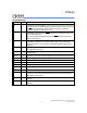
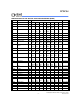
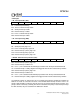
Following tables show the interrupt informations and priority definitions.
Eight-source interrupt informations:
INTERRUPT
SOURCE
VECTOR
ADDRESS
POLLING
SEQUENCE WITHIN
PRIORITY LEVEL
ENABLE
REQUIRED
SETTINGS
INTERRUPT
TYPE
EDGE/LEVEL
External Interrupt 0 03H 0 (highest) IE.0 TCON.IT0
Timer/Counter 0 0BH 1 IE.1 -
External Interrupt 1 13H 2 IE.2 TCON.IT1
Timer/Counter 1 1BH 3 IE.3 -
Serial Port 23H 4 IE.4 -
Timer/Counter 2 2BH 5 IE.5 -
External Interrupt 2 33H 6 XICON.EX2 XICON.IT2
External Interrupt 3 3BH 7 (lowest) XICON.EX3 XICON.IT3
*Timer/Counter
***TL0, TH0, TL1, TH1, TL2, TH2, RCAP2L, RCAP2H
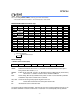
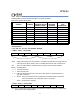
***TMOD - Timer 0, 1 mode (89H)
GATE C//T M1 M0 GATE C//T M1 M0
TIMER0
TIMER1
GATE: Gating control. When set, Timer/counter x is enabled only while INTx pin is high and TRx
control pin is set. When cleared, Timer x is enabled whenever the TRx conrol bit is set.
C//T: Timer or Counter Selector. Cleared for timer operation. Set for counter operation.
M1 M0: Operating Mode
0 0: 13-bit Timer/Counter.
0 1: 16-bit Timer/Counter.
1 0: 8-bit auto-reload Timer/Counter. THx holds a value which is to be reloaded into TLx
each time it overflows.
1 1: Timer 0: TL0 is an 8-bit timer/counter controlled by the standard Timer 0 control bits.
TH0 is an 8-bit timer only controlled by Timer 1 control bits.
Timer 1: Timer/counter 1 stopped.
***TCON - Timer 0, 1 Control (88H)
TF1 TR1 TF0 TR0 IE1 IT1 IE0 IT0
TF1: Timer 1 overflow flag. Set by hardware on timer/counter overflow. cleared by hardware when
processor vectors to interrupt routine.