
Manual


W78C54
Publication Release Date: December 1997
- 15 - Revision A2
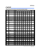
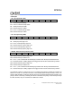
Data Read Cycle
External Data Memory Read Cycle (see Figure 7)
PARAMETER SYMBOL MIN. TYP. MAX. UINT NOTES
ALE Low to RD Low
T
DAR
3 Tcp-∆
3 Tcp
3 Tcp+∆
nS 1, 2
RD Low to Data Valid
T
DDA - - 4 Tcp nS 1
Data hold After RD High
T
DDH 0 - 2 Tcp nS
Data Float After RD High
T
DDZ 0 - 2 Tcp nS
RD Pulse Width
T
DRD
6 Tcp-∆
6 Tcp
6 Tcp+∆
nS 2
Notes:
1. Data Memory access time is 5 Tcp.
2. ∆ is 20 ns (due to buffer driving delay and wire loading.
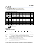
Data Write Cycle
External Data Memory Write Cycle (see Figure 8)
PARAMETER SYMBOL MIN. TYP. MAX. UINT NOTE
ALE Low to WR Low
T
DAW
3 Tcp-∆
3 Tcp
3 Tcp+∆
nS *
Data Valid to WR Low
T
DAD
1 Tcp-∆
--nS
Data hold After WR High
T
DWD
1 Tcp-∆
--nS
WR Pulse Width
T
DWR
6 Tcp-∆
6 Tcp
6 Tcp+∆
nS *
*Note: ∆ is 20 ns (due to buffer driving delay and wire loading)
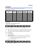
Port Access Cycle
Port Access Cycle (see Figure 9)
PARAMETER SYMBOL MIN. TYP. MAX. UINT
Port Input Setup to ALE Low TPDS 1Tcp - - nS
Port Input Hold After ALE Low TPDH 0--nS
Port Output to ALE High TPDA
1Tcp-∆
--nS
Note: Ports are read during S5P2, and output data becomes available at the end of S6P2. The timing data are referenced to
ALE, since it provides a convenient reference.