
Manual

W78C54
- 8 -
Note: In column BIT_ADDRESS, SYMBOL, containing ( ) item means the bit address.
* SFRs modified or added to the W78C52. + Reset value depends on reset condition.
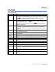
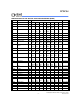
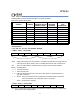
W78C54 SFRs address location map:
F8 FF
F0 + B F7
E8 EF
E0 + ACC E7
D8 +P4 DF
D0 + PSW D7
C8 +T2CON RCAP2L RCAP2H TL2 TH2 CF
C0 +XICON C7
B8 + IP BF
B0 + P3 B7
A8 + IE AF
A0 + P2 A7
98 + SCON SBUF 9F
90 + P1 97
88 + TCON TMOD TL0 TL1 TH0 TH1 AUXR 8F
80 +P0 SP DPL DPH PCON 87
Notes:
1. + SFR is bit-addressable.
2. is additional defined function.
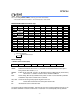
Power-off Flag
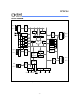
***PCON - Power Control (87H)
SMOD SMOD0
-
POF
GF1 GF0 PD IDL
SMOD: Double baud rate bit. When set to a 1, the baud rate is doubled when the serial port is
being used in either modes 1, 2, 3.
SMOD0: Enable FE bit in SCON. This bit is an alternative switch of SM0 and FE (Frame Error)
bit. When set to a 1, SCON.7 means a FE bit, otherwise a SM0 bit.
POF: Power off flag. Bit is set by hardware when power on reset. It can be cleared by software
to determine chip reset is a warm boot or cold boot.
GF1, GF0: These two bits are general-purpose flag bits for the user.
PD: Power down mode bit. Set it to enter power down mode.
IDL: Idle mode bit. Set it to enter idle mode.
The power-off flag is located at PCON.4. This bit is set when V
DD has been applied to the part. It can
be used to determine if a reset is a warm boot or a cold boot if it is subsequently reset by software.