
Instruction Manual


W78C58
- 14 -
AC CHARACTERISTICS
The AC specifications are a function of the particular process used to manufacture the part, the
ratings of the I/O buffers, the capacitive load, and the internal routing capacitance. Most of the
specifications can be expressed in terms of multiple input clock periods (T
CP), and actual parts will
usually experience less than a ±20 nS variation. The numbers below represent the performance
expected from a 0.8 micron CMOS process when using 2 and 4 mA output buffers.
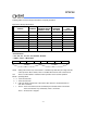
Clock Input Waveform
T
T
XTAL1
F
CH
CL
OP,
T
CP
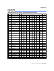
PARAMETER SYMBOL MIN. TYP. MAX. UNIT NOTES
Operating Speed FOP 0 - 40 MHz 1
Clock Period TCP 25 - - nS 2
Clock High TCH 10 - - nS 3
Clock Low TCL 10 - - nS 3
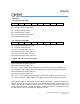
Notes:
1. The clock may be stopped indefinitely in either state.
2. The T
CP specification is used as a reference in other specifications.
3. There are no duty cycle requirements on the XTAL1 input.
Program Fetch Cycle
External Program Memory Fetch Cycle (see Figure 6)
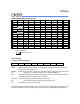
PARAMETER SYMBOL MIN. TYP. MAX. UINT NOTES
Address Valid to ALE Low TAAS
1TCP -∆
--nS
Address Hold After ALE Low TAAH
1TCP -∆
--nS1
ALE Low to PSEN Low
T
APL
1TCP -∆
1T
CP
1TCP+∆
nS
PSEN Low to Data Valid
T
PDA --2TCP nS 2
Data Hold After PSEN High
T
PDH 0-1TCP nS 3
Data Float After PSEN High
T
PDZ 0-1TCP nS
ALE Pulse Width TALW
2TCP -∆
2T
CP
2TCP +∆
nS 4
PSEN Pulse Width
T
PSW
3TCP -∆
3T
CP
3TCP +∆
nS 4