
User guide


W78C801
Publication Release Date: February 1999
- 17 - Revision A3
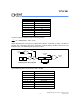
PACKAGE DIMENSIONS
40-pin DIP
Seating Plane
1. Dimension D Max. & S include mold flash or
tie bar burrs.
2. Dimension E1 does not include interlead flash.
3. Dimension D & E1 include mold mismatch and
are determined at the mold parting line.
6. General appearance spec. should be based on
final visual inspection spec.
.
1.3721.2190.0540.048
Notes:
Symbol
Min.
Nom.
Max. Max.
Nom.
Min.
Dimension in inch Dimension in mm
0.050 1.27
0.210
5.334
0.010
0.150
0.016
0.155
0.018
0.160
0.022
3.81
0.406
0.254
3.937
0.457
4.064
0.559
0.008
0.120
0.670
0.010
0.130
0.014
0.140
0.203
3.048
0.254
3.302
0.356
3.556
0.540
0.5500.545
13.72
13.97
13.84
17.01
15.24
14.986
15.494
0.6000.590
0.610
2.286 2.54 2.7940.090 0.100
0.110
A
B
c
D
e
A
L
S
A
A
1
2
E
B
1
1
e
E
1
a
2.055 2.070 52.20 52.58
015
0.090
2.286
0.6500.630 16.00 16.51
protrusion/intrusion.
4. Dimension B1 does not include dambar
5. Controlling dimension: Inches.
150
e A
A
a
c
E
Base Plane
1
A
1
e
L
A
S
1
E
D
1
B
B
40
21
201
2
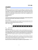
44-pin PLCC
44 40
39
29
2818
17
7
61
L
c
1
b
2
A
H
D
D
e
b
E
H
E
y
A
A
1
Seating Plane
D
G
G
E
Symbol
Min.
Nom.
Max. Max.
Nom.
Min.
Dimension in inch Dimension in mm
A
e
H
E
L
y
b
c
D
A
A
1
2
E
b
1
H
D
G
G
D
E
Notes:
on final visual inspection spec.
4. General appearance spec. should be based
3. Controlling dimension: Inches
protrusion/intrusion.
2. Dimension b1 does not include dambar
flash.
1. Dimension D & E do not include interlead
0.020
0.145
0.026
0.016
0.008
0.648
0.590
0.680
0.090
0.150
0.028
0.018
0.010
0.653
0.610
0.690
0.100
0.050 BSC
0.185
0.155
0.032
0.022
0.014
0.658
0.630
0.700
0.110
0.004
0.508
3.683
0.66
0.406
0.203
16.46
14.99
17.27
2.296
3.81
0.711
0.457
0.254
16.59
15.49
17.53
2.54
1.27
4.699
3.937
0.813
0.559
0.356
16.71
16.00
17.78
2.794
0.10
BSC
16.7116.5916.46
0.6580.6530.648
16.00
15.4914.99
0.6300.610
0.590
17.7817.53
17.27
0.700
0.690
0.680
θ