
User guide

W78C801
- 8 -
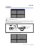
Table.1 Priority level for simultaneous requests of the same priority interrupt sources
Source Flag Priority level Vector Address
External Interrupt 0 IE0 (highest) 0003H
External Interrupt 5 IQ5 0053H
Timer 0 Overflow TF0 000BH
External Interrupt 6 IQ6 005BH
External Interrupt 1 IE1 0013H
External Interrupt 2 IQ2 003BH
External Interrupt 7 IQ7 0063H
Timer 1 Overflow TF1 001BH
External Interrupt 3 IQ3 0043H
External Interrupt 8 IQ8 006BH
External Interrupt 4 IQ4 004BH
External Interrupt 9 IQ9 (lowest) 0073H
Watchdog Timer
The Watchdog timer is a free-running timer which can be programmed by the user to serve as a
system monitor, a time-base generator or an event timer. It is basically a set of dividers that divide
the system clock. The divider output is selectable and determines the time-out interval. When the
time-out occurs a system reset can also be caused if it is enabled. The main use of the Watchdog
timer is as a system monitor. This is important in real-time control applications. In case of power
glitches or electro-magnetic interference, the processor may begin to execute errant code. If this is
left unchecked the entire system may crash. The watchdog time-out selection will result in different
time-out values depending on the clock speed. The Watchdog timer will de disabled on reset. In
general, software should restart the Watchdog timer to put it into a known state. The control bits that
support the Watchdog timer are discussed below.
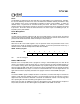
Watchdog Timer Control Register
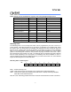
Bit: 7 6 5 4 3 2 1 0
ENW CLRW WIDL - - PS2 PS1 PS0
Mnemonic: WDTC Address: 8FH
ENW : Enable watch-dog if set.
CLRW : Clear watch-dog timer and prescaler if set. This flag will be cleared automatically
WIDL : If this bit is set, watch-dog is enabled under IDLE mode. If cleared, watch-dog is disabled
under IDLE mode. Default is cleared.
PS2, PS1, PS0 : Watch-dog prescaler timer select. Prescaler is selected when set PS2−0 as follows: