
User guide

W78C801
Publication Release Date: February 1999
- 9 - Revision A3
PS2 PS1 PS0 PRESCALER SELECT
0 0 0 2
0 1 0 4
0 0 1 8
0 1 1 16
1 0 0 32
1 0 1 64
1 1 0 128
1 1 1 256
The time-out period is obtained using the following formula:
1
OSC
2 PRESCALER 1000 12 mS
14
×× × ×
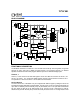
Before Watchdog time-out occurs, the program must clear the 14-bit timer by writing 1 to WDTC.6
(CLRW). After 1 is written to this bit, the 14-bit timer , prescaler and this bit will be reset on the next
instruction cycle. The Watchdog timer is cleared on reset.
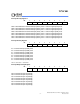
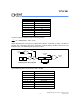
OSC 1/12
PRESCALER
14-BIT TIMER
CLEAR
CLRW
EXTERNAL
RESET
INTERNAL
RESET
WIDL
IDLE
ENW
Watchdog Timer Block Diagram
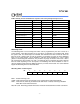
Typical Watch-Dog time-out period when OSC = 20 MHz
PS2 PS1 PS0 WATCHDOG TIME-OUT PERIOD
0 0 0 19.66 mS
0 1 0 39.32 mS
0 0 1 78.64 mS
0 1 1 157.28 mS
1 0 0 314.57 mS
1 0 1 629.14 mS
1 1 0 1.25 S
1 1 1 2.50 S