
Instruction Manual

W90P710CD/W90P710CDG
Publication Release Date: September 19, 2006
- 323 - Revision B2
BITS DESCRIPTIONS
[6] Reserved -
[5] AC_BCLK_PU_EN
This bit controls the AC_BCLK pin pull-high resister.
AC_BCLK_PU_EN=0, the AC_BCLK pin pull-high resister will be
disabled
AC_BCLK_PU_EN=1, the AC_BCLK pin pull-high resister will be
enabled
The AC_BCLK_PU_EN bit is read/write.
[4] AC_R_FINISH
AC-link read data ready bit. When read data indexed by previous
frame is shifted into ACTL_ACIS2, the AC_R_FINISH bit will be
set to 1 automatically. After CPU read out the read data,
AC_R_FINISH bit will be cleared to 0.
AC_R_FINISH=0, read data buffer has been read by CPU
AC_R_FINISH=1, read data buffer is ready for CPU read
The AC_R_FINISH bit is read only
[3] AC_W_FINISH
AC-link write frame finish bit. When writing data to register
ACTL_ACOS0, the AC_W_FINISH bit will be set to 1
automatically. After AC-link interface shift out the register
ACTL_ACOS0, the AC_W_FINISH bit will be cleared to 0.
AC_W_FINISH=0, AC-link control data out buffer has been shifted
out to codec by CPU and data out buffer is empty.
AC_W_FINISH=1, AC-link control data out buffer is ready to be
shifted out(After users have wrote data into register
ACTL_ACOS0)
The AC_W_FINISH bit is read only
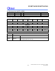
31 30 29 28 27 26 25 24
Reserved
23 22 21 20 19 18 17 16
Reserved
15 14 13 12 11 10 9 8
Reserved
7 6 5 4 3 2 1 0
Reserved
AC_BCLK_
PU_EN
AC_R_FINI
SH
AC_W_FINI
SH
AC_W_RE
S
AC_C_RES Reserved