
Instruction Manual

W90P710CD/W90P710CDG
Publication Release Date: September 19, 2006
- 325 - Revision B2
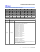
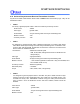
BITS DESCRIPTIONS
[31:5] Reserved -
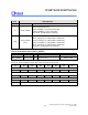
[4] VALID_FRAME
Frame valid indicated bits
VALID_FRAME=1, any one of slot is valid
VALID_FRAME=0, no any slot is valid
The VALID_FRAME bits are read/write
[3:0]
SLOT_VALID
[3:0]
Slot valid indicated bits
SLOT_VALID[0]= 1/0, indicate Slot 1 valid/invalid
SLOT_VALID[1]= 1/0, indicate Slot 2 valid/invalid
SLOT_VALID[2]= 1/0, indicate Slot 3 valid/invalid
SLOT_VALID[3]= 1/0, indicate Slot 4 valid/invalid
The SLOT_VALID[3:0] bits are read/write
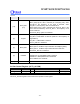
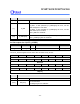
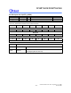
The AC-link output slot 1 (ACTL_ACOS1)
REGISTER ADDRESS R/W DESCRIPTION RESET VALUE
ACTL_ACOS1
0xFFF0_9034 R/W
AC-link out slot 1
0x0000_0080
The ACTL_ACOS1 register store the slot 1 value to be shift out by AC-link.
31 30 29 28 27 26 25 24
Reserved
23 22 21 20 19 18 17 16
Reserved
15 14 13 12 11 10 9 8
Reserved
7 6 5 4 3 2 1 0
R_WB R_INDEX[6:0]