
Instruction Manual

W90P710CD/W90P710CDG
Publication Release Date: September 19, 2006
- 379 - Revision B2
Continued
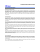
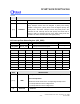
BITS DESCRIPTIONS
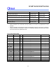
[5:3]
Reserved
Reserved
[2:0]
PRIORITY
Priority Level
Every interrupt source must be assigned a priority level during
initiation. Among them, priority level 0 has the highest priority and
priority level 7 the lowest. Interrupt sources with priority level 0 are
promoted to FIQ. Interrupt sources with priority level other than 0
belong to IRQ. For interrupt sources of the same priority level that
located in the lower channel number has higher priority.
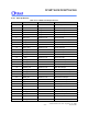
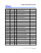
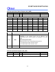
AIC Interrupt Raw Status Register (AIC_IRSR)
REGISTER ADDRESS R/W DESCRIPTION RESET VALUE
AIC_IRSR
0xFFF8_2100
R
Interrupt Raw Status Register
0x0000_0000
31 30 29 28 27 26 25 24
IRS31 IRS30 IRS29 IRS28 IRS27 IRS26 IRS25 IRS24
23 22 21 20 19 18 17 16
IRS23 IRS22 IRS21 IRS20 IRS19 IRS18 IRS17 IRS16
15 14 13 12 11 10 9 8
IRS15 IRS14 IRS13 IRS12 IRS11 IRS10 IRS9 IRS8
7 6 5 4 3 2 1 0
IRS7 IRS6 IRS5 IRS4 IRS3 IRS2 IRS1 RESERVE
D
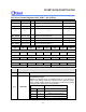
BITS DESCRIPTIONS
[31:1]
IRSx
This register records the intrinsic state within each interrupt channel.
IRS
x: Interrupt Status
Indicate the intrinsic status of the corresponding interrupt source
0 = Interrupt channel is in the voltage level 0
1 = Interrupt channel is in the voltage level 1
[0]
Reserved
Reserved