RAIS INSERT 60 FIREPLACE INSERT ENCLOSURE INSTALLATION INSTRUCTIONS RAIS A/S Industrivej 20 9900 Frederikshavn Denmark TEL: +45 98 47 90 33 RAIS, Inc. 1011 Highway 52 West Portland, TN 37148 USA TEL: 615-325-1700 MODEL NO: 4034801100 Report #138-S-15-2 INSTALLER: Leave this manual with the appliance. CONSUMER: Retain this manual for future reference.
REFER TO THE RAIS INSERT 60 USER’S MANUAL FOR INFORMATION ABOUT OPERATION AND REQUIRED MAINTENANCE FOR YOUR FIREPLACE INSERT. PRODUCT SAFETY THIS FIREPLACE INSERT ENCLOSURE IS A LISTED COMPONENT FOR AND IS INTENDED FOR USE WITH THE RAIS INSERT 60 WOOD-BURNING FIREPLACE INSERT ONLY. DO NOT USE OTHER PRODUCTS NOT SPECIFIED OR LISTED FOR USE WITH THIS ENCLOSURE. WARNING: IF THE ENCLOSURE AND FIREPLACE INSERT ARE NOT PROPERLY INSTALLED, A HOUSE FIRE MAY RESULT.
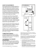
from the top of the support structure to the ceiling above Insert 60 may be no less than 60 ½” (1537mm). See Fig. 5 on page 5 for support structure information. The face of the support structure should be covered with non-combustible materials only. Simply add the height of the support structure to the non-combustible material height shown in Fig. 6 on page 5.
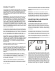
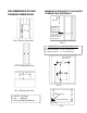
Refer to the adjacent illustration for minimum clearance requirements. Typical framing along with rough framing dimensions are shown in the Figs.2, 3 & 4 on page 5 of these instructions. The actual framing details will vary depending on the placement of your enclosure and Insert 60. It is important to take care when framing to be sure that the area under the enclosure is level and that all framing members are plumb.
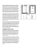
RECOMMENDED ROUGH FRAMING DIMENSIONS MINIMUM CLEARANCES TO ADJACENT COMBUSTIBLE MATERIALS Ceiling D D = 60 1/2” (1537mm) Minimum B A Top of enclosure support structure when enclosure is elevated off floor FIG. 2 Framing Front View FIG. 5 Combustible / Non-Combustible Material Limits E = 39 3/8” (1000mm) F = 60 3/4” (1543mm) G = 28 3/4” (730mm) H = 24 1/4” (616 mm) J = 25 5/8” (651mm) K = 10 7/8” (276mm) C Non-Combustible Materials Only E 5 FIG. FIG. 3 Framing Side View J B F G H C K FIG. 6 FIG.
HEARTH REQUIREMENTS L = 34 1/2” (875mm) Min. M = 16” (405 mm) Min. USA M = 18” (457mm) Min. Canada N = 8” (203mm) Min. When using the Insert 60 in the Fireplace Insert Enclosure, the hearth protection requirements are different than when installing the Insert 60 in an existing masonry fireplace. The enclosure has been designed to elevate the Insert 60 to the minimum distance above the combustible floor where no thermal floor protection is required.
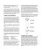
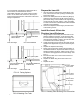
If a wood storage compartment is built below the insert enclosure, it should be lined with noncombustible materials. If the wood storage compartment is on the same level as the floor, the floor protection should extend into the entire base of the wood storage compartment. 13/16” (20mm) Max. Non-Combustible Tile Backer Board Insert 60 Flange Combustible Wallboard Non-CombustibleTile 13/16” (20mm) Max.