
User manual


Beijing Raisecom Science & Technology Co., Ltd.
http://www.raisecom.com
- 13 -
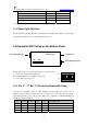
3.3 Dip-switch SW2 Setup on the Bottom Panel
3.3.1 The 1
st
~ 6
th
Bits Definition
1
st
bit 2
nd
bit 3
rd
bit 4
th
bit 5
th
bit 6
th
bit
Definition
TX CLK
phase
RX CLK
phase
PCM30/31
Option
CRC
function
option
Loop-back
test
Loop-back
option
ON
Negative Negative PCM30 Disable
Loop-back Local
Loop-back
OFF
Positive Positive PCM31 Enable
Normal Remote
Loop-back
Since the relationships between V.35 data and clock phase are different on different brand
Routers, TX CLK and RX CLK phase options are used to solve the problem. When TX CLK
and RX CLK are both set to Positive, the RC802-30B-FV35 has passed the test at the V.35
synchronous WAN interface of CISCO series Routers.
TX CLK positive: TD signal will be sampled at the falling edge of TCK clock signal
TX CLK negative: TD signal will be sampled at the rising edge of TCK clock signal
RX CLK positive: RD signal will be sampled at the falling edge of RCK clock signal
RX CLK negative: RD signal will be sampled at the rising edge of RCK clock signal
PCM30/31 option. When other equipment (i.e. DXC, MUX) in the link requires the frame
format to be PCM30, the modem shall be configured to PCM30 (N≤30); when requires the
frame format to be PCM31, the modem shall be configure to PCM31 (N≤31). The local and
remote sites shall have the same configuration.
CRC option. Disable/Enable the CRC function according to the link requirement. The local
and remote sites shall have the same configuration.
Loop-back test is the auxiliary function used for users to test and diagnose the equipment and
link.
Local Loop-back: It is actual local bidirectional loop-back. Internal loop-back for V.35 interface,
external loop-back for fiber optical interface.
As the above figure, the 5
th
and 6
th
bits of SW2 are switched to ON, and the 1
st
~ 5
th
bits are set to
configure the customized bandwidth. The loop-back status can be viewed at the port of local and
remote Router.