
User manual

Beijing Raisecom Science & Technology Co., Ltd.
http://www.raisecom.com
- 9 -
Chapter 3. Preparation
Please read this chapter carefully before installing the equipment.
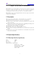
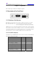
3.1 Description of the Front Panel
TX RX
DCE
ALM
PWR
3.1.1 Definition of the Indicators
PWR. Power supply indicator (green): Steady on, built-in power works in good condition.
ALM. Alarm indicator (red): Local receiving signal error alarm, (The status is ON)
Remote receiving signal error alarm, (The status is FLASH)
ALM indicators are used to check the E1 signals that are generated from the optical receiving link.
In the extended connection solutions in Chapter 2.3, if errors occur at the remote transmit and
receive link, then ALM can be used to indicate this alarm. If users do not adopt Raisecom V.35 to
fractional E1 interface converter (i.e. RC903-V35FE1), then the remote alarm is invalid.
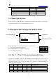
3.1.2 V.35 (DCE) Interface
V.35 interface adopts V.35/HDB26 Female connector. It can be connected by standard DTE cable.
The definitions of the pins are as follows:
Pin Name Input/Output Pin Number
Chassis Ground — CGND - 1
Signal Ground — GND - 7
Receive Data (A) — RD(A) O 3
Receive Data (B) — RD(B) O 21
Receive Timing (A) — RCK(A) O 17
Receive Timing (B) — RCK(B) O 25
Send Data (A) — TD(A) I 2
Send Data (B) — TD(B) I 11
Send Timing (A) — TCK(A) O 15
Send Timing (B) — TCK(B) O 23
Terminal Timing (A) — SCTE(A) I 24
Terminal Timing (B) — SCTE(B) I 16