RC802/804-240B 8E1 Modular Fiber-Optic Multiplexer (Rev. M) User Manual Raisecom Technology Co., Ltd.
Raisecom Technology Co., Ltd 1. Cautions Please read the following notices carefully before installing and using the device, Raisecom does not respond to any loss that caused by violating safety notice. This series fiber-optic multiplexer is integrated device that has precise elements, please avoid violent shakes and impacts, and do not disassemble or maintain the device yourself. If it is required, please do it under the guide of our technical staff following in the steps of anti static.
Raisecom Technology Co., Ltd Contents 1. Cautions ...........................................................................................................................................1 2. Overview ..........................................................................................................................................3 2.1. 2.2. 2.3. 3. Parameters.......................................................................................................................................
Raisecom Technology Co., Ltd 2. Overview 2.1. Introduction RC800-240B series fiber-optic multiplexers are ideal fiber-optic transmission devices for point-to-point networks, medium-sized and small capacity networks, such as wireless communication base stations, private communication networks, and switching networks. The transmission capacity of RC800-240B is 8 E1 channels. RC802-240B and RC804-240B fiber-optic multiplexers are the modular versions of RC800-240B.
Raisecom Technology Co.
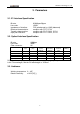
Raisecom Technology Co., Ltd 3. Parameters 3.1. E1 Interface Specification Bit rate: Line code: Impedance of interface: Electrical characteristics: Transfer characteristics: Input jitter tolerance: 2048Kbps±50ppm HDB3 75Ω (unbalanced) or 120Ω (balanced) complies with ITU-T G.703 complies with ITU-T G.823, G.724 complies with ITU-T G.823, G.724 3.2.
Raisecom Technology Co., Ltd 4. How to use 4.1.
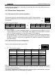
Raisecom Technology Co., Ltd sent through the optical link, so that they are accurate only when the optical receiving is working in good condition. 4.2. DIP-switches Configuration 4.2.1. Dip-switches for E1 Interface Impedance There are 8 groups of 4-bit dip-switches, SW1 to SW8. These switches cannot be managed by network management software, so they must be set manually.
Raisecom Technology Co., Ltd • 5th bit: loop-back type options This switch is used to choose “remote loop-back” or “local loop-back” when performing the E1 loop-back operations.
Raisecom Technology Co., Ltd 5. Installation and Test 5.1. Inspect after Opening Please first check if the models and part numbers are in consistence, and also check if the equipments are damaged. 5.2. Preparation before Installation z z z z z z z Carefully read this manual Prepare all kinds of the cable. Ensure that they are not short-circuited. Refer to Appendix A for cable making. Ensure RC004-16 is properly installed, and the chassis is well connected with the ground.
Raisecom Technology Co., Ltd If using 120 Ohm balanced interface, users can connect the DB37 male interface with DB37 female-connector twisted-pair. z Optical interface Plug the SC fiber tail into optical interface (push hard until to the deep end). If not sure about transmission direction, it’s advised first to turn on the power of device and then plug in the fiber cable. 5.3.3. Applying the Power Supply When PS is turned on, the PWR indicator shall be on.
Raisecom Technology Co., Ltd z LOS red indicator of E1 sub-channel is on Answer: Loss alarm of RX signal at E1 sub-channel, no HDB3 signal is received. Check whether all E1 ports are connected well, or whether 75Ω cables are reversely connected, or whether the wires of 120Ω cables are in correct sequence. If LOS alarm occurs at unused E1 sub-channel, press “mask” button to “on” to musk the alarm after finishing the configuration of device.
Raisecom Technology Co., Ltd 6. Appendix A Introduction of Cable Making A.1 E1 Cable • 75 Ohm signal adopts DB37 coaxial adapter: SYV 75-2-2 coax cable, the distance shall not be longer than 200m. First pick out the CC3-K3 connector from the accessories, and release the tail protecting jack. Secondly, separate the core from the shield, and put the tail protecting jack on it. Solder the strand with the core of the CC3-K3 connector. Solder the cable shield with the shield of the CC3-K3 connector.
Raisecom Technology Co., Ltd @2005 Raisecom Technology Co., Ltd. All trademarks are the property of their respective owners. Technical information may be subject to change without prior notification.