
User manual


Raisecom Technology Co., Ltd
7
OFF OFF ON The first power supply works abnormally, the second
works normally but the main circuit works
abnormally.
OFF OFF OFF Not powered on or neither of the power supply
module works normally.
4
CONSOL
E
Local management port which connects to management PC
5
Ethernet
port
indicator
Green/or
ange
1-8 fast Ethernet ports. And each port has two indicators: LNK/ACT (green)
and 100M indicator (orange).
LNK/ACT, flashing indicates data is being received;
100M, ON indicates the speed of fast Ethernet is 100M and OFF indicates
10M.
6
1-8 E1
indicator
Red Each E1 circuit has three indicators, from top to bottom are:
(Top) LOS: Loss of Signal (local).
(Middle) LAL: local general alarm, including AIS (alarm indication signal),
LOF (loss of frame), CRC (cyclic redundancy check).
(Bottom) RAL: remote general alarm, including LOS, AIS, LOF, CRC.
*note: when both LOS and LAL are ON at the same time, this indicates GID
alarm.
7
1-8 E1
connector
DB37 connector which connects with special cable.
8
9-16 E1
indicator
Red Each E1 circuit has three indicators, from top to bottom are:
(Top) LOS: Loss of Signal (local).
(Middle) LAL: local general alarm, including AIS (alarm indication signal),
LOF (loss of frame), CRC (cyclic redundancy check).
(Bottom) RAL: remote general alarm, including LOS, AIS, LOF, CRC.
*note: when both LOS and LAL are ON at the same time, this indicates GID
alarm.
9
9-16 E1
connector
DB37 connector which connects with special cable.
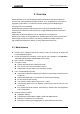
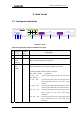
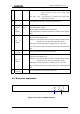
4.2. Rear panel explanation
ON
OFF
21
Figure 4-2 rear panel of RC953-8FE16E1